Sharp AR-F151 (serv.man7) Service Manual ▷ View online
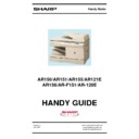
CODE: 00ZARF151/A1E
DIGITAL COPIER
AR-150
AR-155
AR-155
MODEL
AR-F151
[ 1 ] GENERAL . . . . . . . . . . . . . . . . . . . . . . . . . . . 1 - 1
[ 2 ] SPECIFICATIONS . . . . . . . . . . . . . . . . . . . . . . 2 - 1
[ 3 ] CONSUMABLE PARTS . . . . . . . . . . . . . . . . . . . 3 - 1
[ 4 ] EXTERNAL VIEWS AND INTERNAL STRUCTURES . . . 4 - 1
[ 5 ] UNPACKING AND INSTALLATION . . . . . . . . . . . . . 5 - 1
[ 6 ] OPERATIONAL DESCRIPTIONS . . . . . . . . . . . . . . 6 - 1
[ 7 ] DISASSEMBLY AND ASSEMBLY . . . . . . . . . . . . . . 7 - 1
[ 8 ] ADJUSTMENTS . . . . . . . . . . . . . . . . . . . . . . . 8 - 1
[ 9 ] SIMULATION, FAX SOFTWARE SWITCH,
TROUBLE CODES . . . . . . . . . . . . . . . . . . . . . 9 - 1
[10] USER PROGRAM . . . . . . . . . . . . . . . . . . . . . . 10 - 1
[11] ELECTRICAL SECTION . . . . . . . . . . . . . . . . . . . 11 - 1
[12] CIRCUIT DIAGRAM . . . . . . . . . . . . . . . . . . . . . 12 - 1
CONTENTS
Parts marked with “ ” are important for maintaining the safety of the set. Be sure to replace these parts with specified
ones for maintaining the safety and performance of the set.
ones for maintaining the safety and performance of the set.
SHARP CORPORATION
(AR-F151)
AR-F151
[5]
UNPACKING AND INSTALLATION
1. COPIER INSTALLATION
Improper installation may damage the copier. Please note the
following during initial installation and whenever the copier is
moved.
following during initial installation and whenever the copier is
moved.
Caution: If the copier is moved from a cool place to a warm
place, condensation may form inside the copier.
Operation in this condition will cause poor copy
quality and malfunctions. Leave the copier at room
temperature for at least 2 hours before use.
Operation in this condition will cause poor copy
quality and malfunctions. Leave the copier at room
temperature for at least 2 hours before use.
Do not install your copier in areas that are:
● damp, humid, or very dusty
● damp, humid, or very dusty
● exposed to direct sunlight
● poorly ventilated
● subject to extreme temperature or humidity changes, e.g.,
near an air conditioner or heater.
The copier should be installed near an accessible power outlet
for easy connection.
for easy connection.
Be sure to connect the power cord only to a power outlet that
meets the specified voltage and current requirements.
Also make certain the outlet is properly grounded.
meets the specified voltage and current requirements.
Also make certain the outlet is properly grounded.
Be sure to allow the required space around the machine for
servicing and proper ventilation.
servicing and proper ventilation.
2. CAUTIONS ON HANDLING
Be careful in handling the copier as follows to maintain the per-
formance of this copier.
formance of this copier.
Do not drop the copier, subject it to shock or strike it against
any object.
any object.
Do not expose the drum cartridge to direct sunlight.
Doing so will damage the surface (green portion) of the drum
cartridge, causing poor print quality.
Doing so will damage the surface (green portion) of the drum
cartridge, causing poor print quality.
Store spare supplies such as drum cartridges and TD
cartridges in a dark place without removing from the package
before use.
cartridges in a dark place without removing from the package
before use.
If they are exposed to direct sunlight, poor print quality may
result.
result.
Do not touch the surface (green portion) of the drum cartridge.
Doing so will damage the surface of the cartridge, causing poor
print quality.
print quality.
8"(20cm)
8"(20cm)
4"
(10cm)
4"
(10cm)
(10cm)
AR-F151
5 – 1
3. CHECKING PACKED COMPONENTS AND
ACCESSORIES
Open the carton and check if the following components and ac-
cessories are included.
cessories are included.
4. UNPACKING
Be sure to hold the handles on both sides of the copier to un-
pack the copier and carry it to the installation location.
pack the copier and carry it to the installation location.
5. REMOVING PROTECTIVE PACKING
MATERIALS
1) Remove pieces of tape and protective cover. Then open the
original cover and remove protective materials (a) and (b).
2) Use a coin (or suitable object) to remove the screw.
Store the screw in the paper tray because it will be used if
the copier has to be moved.
the copier has to be moved.
6. INSTALLING THE TD CARTRIDGE
The TD cartridge replacement required ( ) indicator will light
up when toner is needed. If copying is continued while the
indicator is lit, copies will gradually become lighter until the
copier stops and the indicator begins blinking. Replace the old
TD cartridge by following the procedure given below.
up when toner is needed. If copying is continued while the
indicator is lit, copies will gradually become lighter until the
copier stops and the indicator begins blinking. Replace the old
TD cartridge by following the procedure given below.
Note:
● After the copier stops, it may be possible to make a few
more copies by taking the TD cartridge out of the copier,
shaking it horizontally, then reinstalling it. If copying is
not possible after this operation, replace the TD
cartridge.
shaking it horizontally, then reinstalling it. If copying is
not possible after this operation, replace the TD
cartridge.
● During long copy run of a dark original, the ready ( )
indicator may blink, the indicator light up, and the
copier stop, even though toner is left. The copier will feed
toner up to 2 minutes and then the ready ( ) indicator
will light up. Press the print ( ) key to restart copying.
copier stop, even though toner is left. The copier will feed
toner up to 2 minutes and then the ready ( ) indicator
will light up. Press the print ( ) key to restart copying.
1) Ensure that the bypass tray is open and then open the side
cover while pressing the side cover open button.
2) Remove the CAUTION tape from the front cover and
remove the two protective pins from the fusing unit by pull-
ing the strings upward one at a time.
ing the strings upward one at a time.
3) Push gently on both sides of the front cover to open the
cover.
4) Remove the TD cartridge from the bag. Remove the protec-
tive paper. Hold the cartridge on both sides and shake it
horizontally four or five times.
horizontally four or five times.
Copier
Power cord
Line cord
FAX model
only
FAX model
only
TD cartridge
Drum cartridge
(installed in copier)
4 or 5 times
AR-F151
5 – 2
5) Hold the tab of the protective cover and pull the tab to
remove the cover.
6) Gently insert the TD cartridge until it locks in place.
7) Close the front cover and then the side cover by pressing
the round projections near the side cover open button. The
indicator will go out and the ready ( ) indicator will
light up.
indicator will go out and the ready ( ) indicator will
light up.
Note: When closing the covers, be sure to close the front
cover securely and then close the side cover. If the
covers are closed in the wrong order, the covers may be
damaged.
covers are closed in the wrong order, the covers may be
damaged.
7. LOADING COPY PAPER
Note: This copier is equipped with two paper trays. Load copy
paper into the two paper trays.
1) Raise the handle of the paper tray and pull the paper tray
out until it stops.
2) Remove the pressure plate lock. Rotate the pressure plate
lock in the direction of the arrow to remove it while pressing
down the pressure plate of the paper tray.
down the pressure plate of the paper tray.
3) Store the pressure plate lock which has been removed in
step 2 and the screw which has been removed when un-
packing (see page 4-2, step 2 of REMOVING PROTEC-
TIVE PACKING MATERIALS) in the front of the paper tray.
To store the pressure plate lock, rotate the lock to fix it on
the relevant location.
packing (see page 4-2, step 2 of REMOVING PROTEC-
TIVE PACKING MATERIALS) in the front of the paper tray.
To store the pressure plate lock, rotate the lock to fix it on
the relevant location.
4) Adjust the paper guides on the paper tray to the copy paper
width and length.
Squeeze the lever of paper guide (A) and slide the guide to
match with the width of the paper.
Move paper guide (B) to the appropriate slot as marked on
the tray.
Squeeze the lever of paper guide (A) and slide the guide to
match with the width of the paper.
Move paper guide (B) to the appropriate slot as marked on
the tray.
5) Fan the copy paper and insert it into the tray. Make sure the
edges go under the corner hooks.
Note: Do not load paper above the maximum height line ( ).
Exceeding the line will cause a paper misfeed.
6) Gently push the paper tray back into the copier.
Note: After loading copy paper, to cancel the blinking “P”
Note: After loading copy paper, to cancel the blinking “P”
without restarting copying, press the clear ( ) key.
The “P” in the display will go out and the ready ( ) in-
dicator will light up.
The “P” in the display will go out and the ready ( ) in-
dicator will light up.
Paper guide (B)
Paper guide (A)
AR-F151
5 – 3
Display

