Sharp AR-C200P (serv.man5) Service Manual ▷ View online
Parts marked with “
” are important for maintaining the safety of the set. Be sure to replace these parts with
specified ones for maintaining the safety and performance of the set.
SHARP CORPORATION
SERVICE MANUAL
CONTENTS
Sharp UK Rev.1 05/04
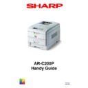
DIGITAL COLOUR PRINTER
MODEL
AR-C200P
AR-M237/M277
AR-M236/M276
[1]
CONFIGURATION
... . . . . . . . . . . . . . . . . . . . . . . . . . . . . . . . . . . . . 7
[2] PARTS REPLACEMENT . . . . . . . . . . . . . . . . . .. . . . . . . . . . . . . . . 1
7
[3] AD
JUSTMENTS. . . . . . . . . . . . . . . . . . . . . . . . . . . . . . . . . . . . . . . . 76
[4] REGULAR MAINTENANCE . . . . . . . . . . . . . . . . . . . . . . . . . . . . . 10
8
[5] TROUBLESHOOTING PROCEDURES. . . . . . . . . . . . . . . . . . . . . 10
9
[6] CON NECTION DIAGRAM . . . . . . . . . . . . . . . . . . . . . . . . . . . . . . . 14
4
[7] PARTS LIST . . . . . . . . . . . . . . . . . . . . . . . . . . . . . . . . . .. . . . . . . . 15
3
APPENDIX A INTERFACE SPECIFICATIONS . . . . . . . . . . . . . . 16
9
APPENDIX B 2ND/3RD TRAY MAINTENANCE . . . . . . . . . . . . . . . 17
3
APPENDIX C ERROR MESSAGES. . . . . . . .
. . . . . . . . . . . . .178
3 /
PREFACE
This manual describes the maintenance procedure of the AR-C200P printer.
The document is produced for maintenance personnel use.
For details on the procedures for handling the printer, see the user documentation.
Note! • The descriptions in this manual are subject to change without prior notice.
• In preparing the document, efforts have been made to ensure that the information in it is accurate.
However, errors may have crept into the document.
Sharp assumes no responsibility for any
damage resulting from, or claimed to be the results of, those repairs, adjustments or modifica-
tions to the printers which are made by users using the manual.
• The parts used for the printers are sensitive and, if handled improperly, may be damaged. It is
strongly recommended that the products are maintained by maintenance staff registered with Sharp.
4 /
CONTENTS
1. CONFIGURATION ........................................................................................... 7
1.1
System Configuration....................................................................................................... 7
1.2
Printer Configuration ........................................................................................................ 8
1.3
Option Configuration ........................................................................................................ 9
1.4
Specifications ................................................................................................................. 10
2. PARTS REPLACEMENT................................................................................ 17
2.1
Precautions in Replacing Parts ...................................................................................... 17
2.2
Parts layout .................................................................................................................... 19
2.3
Replacing Parts.............................................................................................................. 25
2.3.1
Top Cover ......................................................................................................... 27
2.3.2
LED Head / LED Spring / Post-Guide............................................................... 28
2.3.3
Top Cover Unit ................................................................................................. 29
2.3.4
Control Panel Assy/ Control Panel Bezel/ LED Control PWB/ Toner Sensors/
Stacker Full Sensor/ Control Panel/ Control Panel Tape Harness/
Eject Rollers ..................................................................................................... 30
2.3.5
Top Cover Handle/ Top Cover Latch/ Top Cover Latch Spring ........................ 31
2.3.6
Eject Guide Assy .............................................................................................. 32
2.3.7
Cassette Assy/ Front Cover Assy/ Front Cover Inner Baffle ........................... 33
2.3.8
Retard Pad Assy/ Retard Pad Assy Spring ...................................................... 34
2.3.9
Feed Roller and Nudger Roller ......................................................................... 35
2.3.10 Rear Cover ....................................................................................................... 36
2.3.11 Face-Up Tray.................................................................................................... 37
2.3.12 Left Side Cover ................................................................................................. 38
2.3.13 Right Side Cover .............................................................................................. 39
2.3.14 Multipurpose Tray Assy/ Multipurpose Tray Cover Assy/ Links/
Multipurpose Tray Top Cover/ Multipurpose Tray Drive Gear .......................... 40
2.3.15 Drum Contact Assys ......................................................................................... 41
2.3.16 Media Thickness Sensor Assy......................................................................... 42
2.3.17 Registration Roller Assy (A)/ Registration Drive Gear (A) ................................ 43
2.3.18 Registration Roller Assy (B) ............................................................................. 44
2.3.19 Registration Clutch and Registration Motor Assy ............................................. 45
2.3.20 Main Cooling Fan ............................................................................................. 46
2.3.21 Colour Registration Sensor Assy........................................................................47
2.3.22 Duplex Guide Assy ........................................................................................... 48
2.3.23 Electrical Chassis Cooling Fan ......................................................................... 49
2.3.24 Printer Engine Controller PWB ......................................................................... 50
2.3.25 Printer Unit Chassis .......................................................................................... 51
2.3.26 Entrance Cassette Sensor Actuator ................................................................. 52
2.3.27 Entrance Sensor PWB...................................................................................... 53
2.3.28 Entrance MT Sensor Actuator / Entrance Belt Sensor Actuator /
Entrance Waste Chassis Sensor Actuator ...................................................... 54
2.3.29 Fuser Exit Roller ............................................................................................... 55
2.3.30 Exit Sensor Assy .............................................................................................. 56
2.3.31 Fuser Latching Handle (L) ................................................................................ 57
2.3.32 Belt Motor Assy ................................................................................................ 58
2.3.33 Fuser Latching Handle (R) ............................................................................... 59
2.3.34 Main Motor Assy ............................................................................................... 60
2.3.35 Main Feeder Drive Motor .................................................................................. 61
2.3.36 Contact Assy/ Left Plate Assy .......................................................................... 62
2.3.37 Low Voltage Power Supply............................................................................... 63
2.3.38 High voltage power supply ............................................................................... 64
2.3.39 Main Feed Assy ................................................................................................ 65
2.3.40 Cassette/ Left Guide Assy ................................................................................ 66
2.3.41 Cassette/ Right Guide Assy.............................................................................. 67
2.3.42 Fuser Unit ......................................................................................................... 68

