Sharp AR-C170 (serv.man28) Service Manual ▷ View online
AR-C170M TROUBLESHOOTING 11 - 1
[11] TROUBLESHOOTING
[MAIN UNIT]
1. Outline
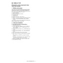
In case of a trouble in the machine, or when a consumable part
has nearly reached or already reach the lifetime, the machine
detects it, analyze it, and displays it on the display section and
notifies the user and the serviceman by a voice message.
has nearly reached or already reach the lifetime, the machine
detects it, analyze it, and displays it on the display section and
notifies the user and the serviceman by a voice message.
The user and the serviceman are bale to perform the proper coun-
termeasures according to a voice message. In case of a trouble,
the machine is stopped to restrict damage to a minimum in addi-
tion to a voice message.
termeasures according to a voice message. In case of a trouble,
the machine is stopped to restrict damage to a minimum in addi-
tion to a voice message.
2. Functions and purposes
1) Assures safety. (The machine is stopped when a trouble is
detected.)
2) Restricts damage to a minimum. (The machine is stopped
when a trouble is detected.)
3) By displaying the trouble content, the trouble position can be
identified immediately and accurately. (An accurate repair
work can be performed, improving the repair efficiency.)
work can be performed, improving the repair efficiency.)
4) By providing a preparatory warning when the lifetime of a con-
sumable part is nearly reached, arrangement of the consum-
able part can be made in advance. (Stopping the machine by
exhaustion of a consumable part is avoidable.)
able part can be made in advance. (Stopping the machine by
exhaustion of a consumable part is avoidable.)
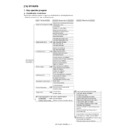
3. Kinds of self diagnostic messages
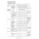
The self diagnostic messages are classified as follows:
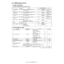
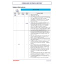
4. Self diagnostic operation
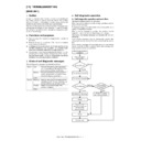
A. Self diagnostic operation and work flow
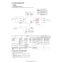
The machine always monitors its own status.
When the machine detects a trouble, it stops operations and dis-
plays a trouble message.
plays a trouble message.
A warning message is provided mainly when a consumable part is
nearly or completely exhausted.
nearly or completely exhausted.
When a warning message is provided, the machine may be
stopped or may not be stopped depending on the message.
stopped or may not be stopped depending on the message.
The trouble and warning messages are indicated with the LCD
and lamps.
and lamps.
Some trouble messages may be automatically cleared after
removing the trouble, and some must be cleared with the simula-
tion.
removing the trouble, and some must be cleared with the simula-
tion.
Some warning messages of consumable parts are automatically
cleared when the trouble is repaired. Some other warning mes-
sages must be cleared by a simulation.
cleared when the trouble is repaired. Some other warning mes-
sages must be cleared by a simulation.
Class 1
User
Troubles and warning messages (paper
jam, consumable part life expiration, etc.)
which can be processed by the user.
jam, consumable part life expiration, etc.)
which can be processed by the user.
Service
Troubles and warning messages (motor
trouble, maintenance, etc.) which can be
processed only by a serviceman.
trouble, maintenance, etc.) which can be
processed only by a serviceman.
Other
—
Class 2
Warning
Warning messages (consumable part life
expiration, etc.) for the user, which are not
directly related to any machine trouble.
expiration, etc.) for the user, which are not
directly related to any machine trouble.
Trouble
Related to a machine trouble. The
machine is stopped.
machine is stopped.
Other
—
Troubleshoot the cause.
YES
NO
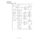
Detects/analyzes
the content.
Trouble/Warning
Warning
Trouble
The machine is stopped.
The content is displayed.
Trouble/Warning
Warning
A consumable
part has reached
its lifetime.
Trouble
Replace or supply
the consumable part.
Cancel the self-
diagnostic message with
the diagnostics
(test commands).
Reset
Standby state
Monitors the machine
conditions.
Repair
AR-C170M TROUBLESHOOTING 11 - 2
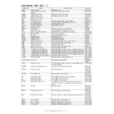
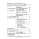
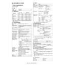
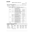
5. List
Main
code
code
Sub
code
Content
C2
10
Transfer charger trouble (Black)
E7
01
Image data memory trouble
10
Shading trouble (Black correction)
11
Shading trouble (White correction)
20
LED controller initial trouble (Black)
21
LED controller initial trouble (Cyan)
22
LED controller initial trouble (Magenta)
23
LED controller initial trouble (Yellow)
24
LED controller output trouble (Black)
25
LED controller output trouble (Cyan)
26
LED controller output trouble (Magenta)
27
LED controller output trouble (Yellow)
28
LED control ASIC connection abnormality
40
Color correction data write abnormality
41
Color correction data transfer abnormality
80
ICU-SCN communication trouble (ICU detection)
90
ICU-PCU communication trouble (ICU detection)
F1
00
Saddle finisher/sorter communication trouble
(Machine detection)
(Machine detection)
02
Saddle finisher transport motor trouble (Saddle
finisher detection)
finisher detection)
03
Saddle finisher paddle motor trouble
06
Saddle finisher slide motor trouble
10
Saddle finisher staple motor trouble (Saddle
finisher detection)
finisher detection)
11
Saddle finisher bundle process motor
abnormality (Saddle finisher detection)
abnormality (Saddle finisher detection)
15
Saddle finisher tray lift motor abnormality (Saddle
finisher detection)
finisher detection)
19
Saddle finisher front alignment motor abnormality
(Saddle finisher detection)
(Saddle finisher detection)
20
Saddle finisher rear alignment motor abnormality
(Saddle finisher detection)
(Saddle finisher detection)
31
Saddle finisher fold sensor trouble
32
Saddle finisher punch unit communication trouble
33
Saddle finisher punch side registration motor
trouble
trouble
34
Saddle finisher punch motor trouble
35
Saddle finisher punch side registration sensor
trouble
trouble
36
Saddle finisher punch registration sensor trouble
37
Saddle finisher/sorter backup RAM trouble
38
Saddle finisher punch backup RAM trouble
39
Saddle finisher punch dust sensor trouble
40
Saddle finisher punch power disconnection
trouble
trouble
83
Sorter push bar motor trouble
89
Sorter bin shift motor trouble
91
Automatic adjustment trouble of the paper sensor
in the sorter bin
in the sorter bin
F2
39
Process thermistor breakdown
40
Toner empty sensor abnormality (Black)
41
Toner empty sensor abnormality (Cyan)
42
Toner empty sensor abnormality (Magenta)
43
Toner empty sensor abnormality (Yellow)
44
Black image density sensor trouble (Transfer belt
surface reflection ratio abnormality)
surface reflection ratio abnormality)
45
Color image density sensor trouble (Calibration
plate surface reflection ratio abnormality)
plate surface reflection ratio abnormality)
58
Process humidity sensor breakdown
70
Developing unit improper cartridge detection
(Black)
(Black)
71
Developing unit improper cartridge detection
(Cyan)
(Cyan)
72
Developing unit improper cartridge detection
(Magenta)
(Magenta)
73
Developing unit improper cartridge detection
(Yellow)
(Yellow)
74
Developing unit CRUM trouble (Black)
75
Developing unit CRUM trouble (Cyan)
76
Developing unit CRUM trouble (Magenta)
77
Developing unit CRUM trouble (Yellow)
78
Trouble of image density sensor for registration
(Transfer belt surface reflection ratio abnormality)
(Transfer belt surface reflection ratio abnormality)
80
Half-tone process control 1st patch error (Black)
81
Half-tone process control 1st patch error (Cyan)
82
Half-tone process control 1st patch error
(Magenta)
(Magenta)
83
Half-tone process control 1st patch error (Yellow)
84
Half-tone process control 2nd patch error (Black)
85
Half-tone process control 2nd patch error (Cyan)
86
Half-tone process control 2nd patch error
(Magenta)
(Magenta)
87
Half-tone process control 2nd patch error
(Yellow)
(Yellow)
90
Half-tone process control limit error
F3
12
Cassette 1 lift up trouble
F6
00
ICU-FAX communication trouble (ICU detection)
01
FAX expansion flash memory abnormality (ICU
detection)
detection)
04
FAX MODEM operation abnormality
20
FAX write protect release
21
Improper combination of the TEL/LIU PWB and
the FAX soft switch.
the FAX soft switch.
97
The FAX-BOX PWB is not one for the AR-
C170M. (FAX detection)
C170M. (FAX detection)
98
Improper combination of the FAX-BOX
destination data and the main unit destination
data
destination data and the main unit destination
data
F7
01
FAX board EEPROM read/write error
F9
00
ICU-PRT communication trouble (ICU detection)
01
PRT DRAM trouble
03
NIC port check error
20
HDD trouble (PRT controller detection)
H2
00
Thermistor open (HL1)
01
Thermistor open (HL2)
H3
00
Fusing section high temperature trouble (THS1)
01
Fusing section high temperature trouble (THS2)
H4
00
Fusing section low temperature trouble (HL1)
01
Fusing section low temperature trouble (HL2)
H5
01
Five continuous detections of POD1 not-reached
jam
jam
L1
00
Mirror feed trouble
Main
code
code
Sub
code
Content
AR-C170M TROUBLESHOOTING 11 - 3
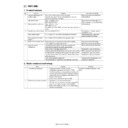
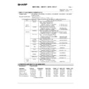
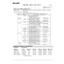
6. Details
L3
00
Mirror return trouble
L4
02
Paper feed motor lock trouble
06
Transfer belt lift motor trouble
07
Transfer belt motor trouble
11
Shift motor trouble
L8
01
Full wave signal not provided
02
Full wave signal width abnormality
04
Main power switch abnormality detection
PF
00
RIC copy inhibit signal reception
U0
00
ICU-OPE communication trouble (ICU/OPE
detection)
detection)
U1
01
FAX battery abnormality
02
RTC read trouble
U2
00
EEPROM read/write error (ICU detection)
11
EEPROM check sum error (ICU detection)
22
FAX backup SRAM memory check sum error
30
Production No. data discrepancy (ICU
⇔
ICU)
80
EEPROM read/write error (SCN)
81
Adjustment value check sum error (SCN)
90
EEPROM read/write error (PCU)
91
Adjustment value check sum error (PCU)
U4
02
ADU alignment plate operation abnormality
U6
00
Desk communication trouble
01
Desk tray 1 lift motor trouble
02
Desk tray 2 lift motor trouble
03
Desk tray 3 lift motor trouble
09
LCC lift motor trouble
10
Desk transport motor trouble
20
LCC communication trouble
21
LCC transport motor trouble
22
LCC 24V power abnormality
50
Desk incompatibility trouble
51
LCC incompatibility trouble
U7
00
RIC communication trouble
UC
02
CPT-ASIC trouble (MFP PWB trouble)
Main
code
code
Sub
code
Content
Main
code
code
Sub
code
Title
Transfer charger trouble (Black)
C2
10
Display
Lamp/Message
Phenomenon Detail
The difference between the
belt surface output and the
K-color patch density output
does not reach the specified
level. (Judged when
installing a new developing
unit.)
belt surface output and the
K-color patch density output
does not reach the specified
level. (Judged when
installing a new developing
unit.)
Section
Transfer
Case 1
Cause
TC-K output abnormality
Check &
Remedy
Remedy
TC-K analog input/output
abnormality.
Replace the TC PWB.
abnormality.
Replace the TC PWB.
Case 2
Cause
MC output abnormality
Check &
Remedy
Remedy
Replace the MC PWB.
Case 3
Cause
Transfer unit trouble
Check &
Remedy
Remedy
Replace the transfer unit.
Case 4
Cause
PCU PWB trouble
Check &
Remedy
Remedy
Replace the PCU PWB.
Case 5
Cause
Connector, harness trouble
(PCU PWB, TC PWB, MC
PWB, transfer unit)
(PCU PWB, TC PWB, MC
PWB, transfer unit)
Check &
Remedy
Remedy
Check contact. Replace the
harness. Replace the PWB.
harness. Replace the PWB.
Main
code
code
Sub
code
Title
Image data memory trouble
E7
01
Display
Lamp/Message
Phenomenon Detail
The ICU image data
memory (SDRAM) cannot
be detected as 256MB or
more. The required SDRAM
capacity for the model is not
provided.
memory (SDRAM) cannot
be detected as 256MB or
more. The required SDRAM
capacity for the model is not
provided.
Section
ICU PWB
Case 1
Cause
The SDRAM of ICU PWB is
not installed. The SDRAM
of ICU PWB is improperly
installed.
not installed. The SDRAM
of ICU PWB is improperly
installed.
Check &
Remedy
Remedy
Check installation of the
SDRAM of ICU ASIC PWB.
SDRAM of ICU ASIC PWB.
Case 2
Cause
The SDRAM of ICU PWB
does not operate properly.
does not operate properly.
Check &
Remedy
Remedy
Use SIM 22-10 to check the
capacity of the SDRAM.
Replace the SDRAM of ICU
PWB.
capacity of the SDRAM.
Replace the SDRAM of ICU
PWB.
Case 3
Cause
ICU PWB abnormality
Check &
Remedy
Remedy
Replace the ICU PWB.
AR-C170M TROUBLESHOOTING 11 - 4
Main
code
code
Sub
code
Title
Shading trouble (Black correction)
E7
10
Display
Lamp/Message
Phenomenon Detail
CCD black reading level
abnormality when the copy
lamp is off.
abnormality when the copy
lamp is off.
Section
CCD unit
Case 1
Cause
Improper installation of the
flat cable to the CCD unit.
flat cable to the CCD unit.
Check &
Remedy
Remedy
Check installation of the flat
cable to the CCD unit.
cable to the CCD unit.
Case 2
Cause
CCD unit abnormality
Check &
Remedy
Remedy
Check the CCD unit.
Case 3
Cause
MFP PWB abnormality
Check &
Remedy
Remedy
Check the MFP PWB.
Main
code
code
Sub
code
Title
Shading trouble (White correction)
E7
11
Display
Lamp/Message
Phenomenon Detail
CCD white reading level
abnormality when the copy
lamp is on.
abnormality when the copy
lamp is on.
Section
CCD unit
Case 1
Cause
Improper installation of the
flat cable to the CCD unit.
flat cable to the CCD unit.
Check &
Remedy
Remedy
Check installation of the flat
cable to the CCD unit.
cable to the CCD unit.
Case 2
Cause
Dirt on the mirror, the lens,
or the reference white plate.
or the reference white plate.
Check &
Remedy
Remedy
Clean the mirror, the lens,
or the reference white plate.
or the reference white plate.
Case 3
Cause
CCD unit abnormality
Check &
Remedy
Remedy
Check the CCD unit.
Case 4
Cause
MFP PWB abnormality
Check &
Remedy
Remedy
Check the MFP PWB.
Main
code
code
Sub
code
Title
LED controller initial trouble
(Black)
(Black)
E7
20
Display
Lamp/Message
Phenomenon Detail
The initial process of the
LED controller cannot be
completed properly.
LED controller cannot be
completed properly.
Section
LED/ICU PWB
Case 1
Cause
Disconnection of the LED
head connector.
head connector.
Check &
Remedy
Remedy
Check connection of the
LED head connector.
LED head connector.
Case 2
Cause
Disconnection of the
harness inside the LED
head.
harness inside the LED
head.
Check &
Remedy
Remedy
Replace the LED head unit.
Case 3
Cause
ICU PWB abnormality
Check &
Remedy
Remedy
Replace the ICU PWB.
Main
code
code
Sub
code
Title
LED controller initial trouble
(Cyan)
(Cyan)
E7
21
Display
Lamp/Message
Phenomenon Detail
The initial process of the
LED controller cannot be
completed properly.
LED controller cannot be
completed properly.
Section
LED/ICU PWB
Case 1
Cause
Disconnection of the LED
head connector.
head connector.
Check &
Remedy
Remedy
Check connection of the
LED head connector
LED head connector
Case 2
Cause
Disconnection of the
harness inside the LED
head.
harness inside the LED
head.
Check &
Remedy
Remedy
Replace the LED head unit.
Case 3
Cause
ICU PWB abnormality
Check &
Remedy
Remedy
Replace the ICU PWB.
Main
code
code
Sub
code
Title
LED controller initial trouble
(Magenta)
(Magenta)
E7
22
Display
Lamp/Message
Phenomenon Detail
The initial process of the
LED controller cannot be
completed properly.
LED controller cannot be
completed properly.
Section
LED/ICU PWB
Case 1
Cause
Disconnection of the LED
head connector.
head connector.
Check &
Remedy
Remedy
Check connection of the
LED head connector
LED head connector
Case 2
Cause
Disconnection of the
harness inside the LED
head.
harness inside the LED
head.
Check &
Remedy
Remedy
Replace the LED head unit.
Case 3
Cause
ICU PWB abnormality
Check &
Remedy
Remedy
Replace the ICU PWB.
Main
code
code
Sub
code
Title
LED controller initial trouble
(Yellow)
(Yellow)
E7
23
Display
Lamp/Message
Phenomenon Detail
The initial process of the
LED controller cannot be
completed properly.
LED controller cannot be
completed properly.
Section
LED/ICU PWB
Case 1
Cause
Disconnection of the LED
head connector
head connector
Check &
Remedy
Remedy
Check connection of the
LED head connector.
LED head connector.
Case 2
Cause
Disconnection of the
harness inside the LED
head.
harness inside the LED
head.
Check &
Remedy
Remedy
Replace the LED head unit.
Case 3
Cause
ICU PWB abnormality
Check &
Remedy
Remedy
Replace the ICU PWB.

