Sharp AR-C150 (serv.man12) FAQ ▷ View online
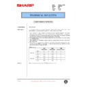
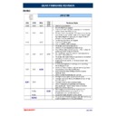
2) REQUIRED TOOLS AND FIRMWARE
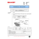
Download to
Creating
Copying
ARC150
Copy ROM's
on ARC150
1 Level converter UKOG-0002QSZZ(with serial
cable)/
2 PC Windows 95/98 operating
environment
3 ADAPTEC 1460B SCSI CARD AND CABLE
4 Download program file Software to write the program
REQUIRED
data from a PC to the AR-C150
Flash ROM (Mainte_1000.exe)
5 PCU MAIN PWB Flash ROM Program File including copy
facility( Bpcuxxx_src.pgm)
6 ICU MAIN PWB Flash ROM Program file including copy
facility( Bicuxxx_src.pgm)
7 Operation control PWB Flash ROM program file including copy
facility (Bopexxx_src.pgm)
8 PCU MAIN PWB Flash ROM Program File Bpcuxxx_d.pgm
9 ICU MAIN PWB Flash ROM Program File Bicuxxx_d.pgm
10 OPE MAIN PWB Flash ROM Program File Bopexxx_d.pgm
11 FLASH 5.EXE UTILITY
12 ICU MAIN PWB Flash ROM Program File 5.10 TO BE USED
WITH FLASH 5 .EXE
13 PCU MAIN PWB Flash ROM Program File 5.08 TO BE USED
WITH FLASH 5 .EXE
14 OPE MAIN PWB Flash ROM Program File 5.06 TO BE USED
WITH FLASH 5 .EXE
15 ICU FLASH CARD ( 16Mbit X 2) Used for ICU DATA &
CREATING SOURCE ROMS FOR ICU, PCU & OPE
16 PCU FLASH CARD ( 16Mbit X 1) Used for PCU DATA
REQUIRED
REQUIRED
17 OPE FLASH CARD ( 16Mbit X 1) Used for OPE DATA
REQUIRED
REQUIRED
NOTE: Items 4-10 are part of the same package
Items 4 - 14 are available on the Sharp technical web site
Necessary items
Using cougar
REQUIRED
REQUIRED
REQUIRED
REQUIRED
REQUIRED
REQUIRED
x3 REQUIRED
REQUIRED
REQUIRED
REQUIRED
REQUIRED
REQUIRED
REQUIRED
REQUIRED
REQUIRED
REQUIRED
REQUIRED
REQUIRED
REQUIRED
REQUIRED
REQUIRED
REQUIRED
REQUIRED
REQUIRED
REQUIRED
3 . Flash ROM version up procedure
(Preliminary procedure)
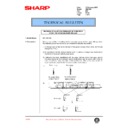
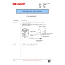
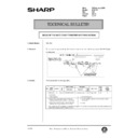
1) Remove the right upper cabinet of the machine. (2 screws)
2) Remove the shield plate and the stopper shaft. (3 screws)
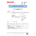
A. By using a computer and the ICU MAIN PWB,
the program data of Flash ROM is written from
the computer to the Flash FOM of the AR-C150
ICU MAIN PWB.
the computer to the Flash FOM of the AR-C150
ICU MAIN PWB.
1) Check that the power of the machine is turned off. Install the Flash
ROM which is to be upgraded (copied) to the write socket of the
ICU MAIN PWB.
ICU MAIN PWB.
2) Connect the personal computer and the level converter.
3) Connect the serial I/F connector on the ICU-MAIN PWB with the
level converter.
4) Turn on the personal computer, and start the Windows.
5) Turn on the power of the machine.
6) Set the data communication speed of the computer.
– 1 – From Start
→
Setup
→
Program, select "Control panel."
– 2 – Click "System."
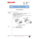
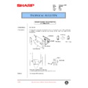
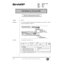
LED 1
LED 2
Write
socket
socket
Read
socket
socket
Level converter
– 3 – Open the "Device manager" tab.
– 4 – Open "Port (COM/LPT)."
– 5 – Select and double-click the "communication port (COM*)"
which is used.
– 6 – Open the "Port setup" tab, and enter "115200" in the
column of bit/sec.
If the above communication speed cannot be set, select and set
one of the following speeds.
one of the following speeds.
9600/19200/38600/57600
– 7 – Close the communication speed setup menu.
7) Set the data communication speed on the machine side.
This setup must be the same as the setup on the computer side.
– 1 – Enter the simulation 49-2 mode.
– 2 – Press the communication speed key which is the same as
the set speed in procedure 8).
(The set communication speed is highlighted.)
(The set communication speed is highlighted.)
– 3 – Cancel the simulation 49-2.
8) Enter the simulation 49-1 mode, and press the EXECUTE key.
(The unit enters the download (Flash ROM writing) mode.)
9) Start the download program on the personal computer.
(Double-click Mainte_1000.exe file.)
10) Select the communication setup from the option menu.
(Set to the communication speed which is the same as the
speed set in procedure 6) and 7).
speed set in procedure 6) and 7).
11) Select the data file which is to be copied (written) to the Flash
ROM installed to the ICU MAIN PWB Write socket in procedure
1).
1).
– 1 – Double-click the Simulation Command List holder.
– 2 – Double-click the Special (Bear) holder.
– 3 – Double-clock the File Program Download.
– 4 – The message of "Program Download OK ?" is displayed.
Press the OK button.
– 5 – Select the data (PWB name) to be written and click the
START button.
– 6 – Select the data to be written and click the OPEN button.
With the above procedure, downloading (writing to the Flash
ROM) is started.
ROM) is started.
(NOTE) Selection of data files to be written determines whether a
source ROM (which includes the latest version program
and the Flash ROM copy program) or a ROM which has
only the latest version program is made.
and the Flash ROM copy program) or a ROM which has
only the latest version program is made.
12) Confirm that downloading (copying to the Flash ROM) is com-
pleted on the computer display and on the LCD display.
It normally takes 5 to 7 minutes to copy (write) to the Flash
ROM.
It normally takes 5 to 7 minutes to copy (write) to the Flash
ROM.
When downloading is normally completed, the following indica-
tions are shown.
tions are shown.
*
The Read and Write LED’s on the ICU MAIN PWB are turned
off.
off.
*
"THE PROGRAM WAS COMPLETE" is displayed on the
LCD.
LCD.
13) Cancel the simulation 49-1 and turn off the power of the
machine.
(NOTE) If the Flash ROM is removed from or installed to the
machine with the machine power ON, the Flash ROM may
be destroyed. Be sure to turn off the power of the machine
before removing or installing the Flash ROM.
be destroyed. Be sure to turn off the power of the machine
before removing or installing the Flash ROM.
14) Remove the Flash ROM (which was upgraded) installed to the
ICU MAIN PWB Write socket in procedure 1).
When another Flash ROM is to be upgraded, install it to the ICU
MAIN PWB Write socket and turn on the power, and perform proce-
dures 11) through 14).
MAIN PWB Write socket and turn on the power, and perform proce-
dures 11) through 14).
B. Method using two Flash ROM sockets on the
AR-C150 ICU MAIN PWB to copy between Flash
ROM’s
ROM’s
1) Check that the power of the machine is OFF. Install the Flash
ROM (of either of ICU MAIN PWB, PCU MAIN PWB, or operation
control PWB) to the ICU MAIN PWB Write socket.
control PWB) to the ICU MAIN PWB Write socket.
2) Install the source Flash ROM (which has the program data of
either of ICU MAIN PWB, PCU MAIN PWN, or operation control
PWB) to the ICU MAIN PWB Read socket.
PWB) to the ICU MAIN PWB Read socket.
3) Turn on the power of the machine.
Copying is started. When copying is completed, the Read and the
Write LED’s on the ICU MAIN PWB are turned off.
It normally takes 30 to 60 sec to copy (write) to the Flash ROM.
Write LED’s on the ICU MAIN PWB are turned off.
It normally takes 30 to 60 sec to copy (write) to the Flash ROM.
4) Turn off the power of the machine, and remove the Flash ROM’s
from the Read and the Write sockets.
(After work)
1) Installed the copied Flash ROM to the specified PWB.
2) Turn on the power of the machine and check that the machine
operates normally.
3) Use the simulation 22-5 to check each ROM version.
4) Install the shield plate and the stopper shift. (3 screws)
5) Attach the right upper cabinet of the machine. (2 screws)
(NOTE)
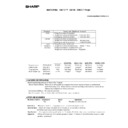
The monitor displays before and after and during the Flash ROM
version up (copy) operation are shown below. If the Flash ROM ver-
sion up operation is not completed normally or if the Flash ROM is not
installed to the socket properly, a trouble code is displayed. In that
case, perform the countermeasures shown in the table below.
version up (copy) operation are shown below. If the Flash ROM ver-
sion up operation is not completed normally or if the Flash ROM is not
installed to the socket properly, a trouble code is displayed. In that
case, perform the countermeasures shown in the table below.
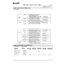
(1) ICU MAIN PWB monitor LED lighting specification
The monitor LED status during copy (write) operation of PC to
Flash ROM and Flash ROM to Flash ROM is shown below.
"Since, in the copy mode of Flash ROM to Flash ROM, the
machine status is indicated only with the monitor LED, there are
many monitor LED lighting patterns."
"While in the copy mode of PC to Flash ROM, the machine status
is indicated on the operation panel or on the PC monitor display,
there are less monitor LED lighting patterns."
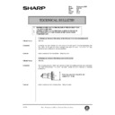
LED 1
LED 2
Write
socket
socket
Read
socket
socket
Display

