Sharp AR-405 (serv.man9) Service Manual ▷ View online
17) Reverse motor speed reduction 867
→
297mm/s (Paper exit
speed reduction)
18) Document feed LED OFF, Document remain LED OFF, Reverse
motor OFF
19) Document feed LED ON, Document remain LED ON, Reverse
motor forward rotation 867mm/s (Paper exit operation)
20) Reverse motor speed reduction 867
→
297mm/s (Paper exit
speed reduction)
21) Document feed LED OFF, Document remain LED OFF, Reverse
motor OFF
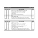
Kind of JAM, error
LED display
Paper feed motor lock
error
error
REMOVE ORIGINAL LED blinks at
the cycle of 2000msec.
the cycle of 2000msec.
Return to 1).
f. EEPROM initializing + all sensors adjustment mode
When the DIP switch is set (3, 5 to ON, 1, 2, 4 to OFF) the push
switch is pressed, the EEPROM is initialized. At that time, the LED
blinks at the cycle of 100msec.
switch is pressed, the EEPROM is initialized. At that time, the LED
blinks at the cycle of 100msec.
After completion of EEPROM initializing, the LED turns ON. In case of
an error in the EEPROM initializing, the LED blinks at the cycle of
2000msec.
an error in the EEPROM initializing, the LED blinks at the cycle of
2000msec.
Then all sensors adjustment is started. At that time, the document
remain LED blinks at the cycle of 100msec. After completion of all
sensors adjustment, the document remain LED turns ON. In case of
an. Error in the all sensors adjustment, the document remain LED
blinks at the cycle of 2000msec.
remain LED blinks at the cycle of 100msec. After completion of all
sensors adjustment, the document remain LED turns ON. In case of
an. Error in the all sensors adjustment, the document remain LED
blinks at the cycle of 2000msec.
*
Only when the EEPROM is successfully completed, the all sensors
adjustment is performed.
adjustment is performed.
Kinds of JAM, error
LED display
EEPROM initializing
error
error
Ready LED blinks at the cycle of
2000msec.
2000msec.
All sensors adjustment
error
error
Document remain LED blinks at the
cycle of 2000msec
cycle of 2000msec
g. Resist sensor adjustment mode
Set the DIP switch (4, 5 to ON, 1, 2, 3 to OFF) and press the push
switch. Each sensor adjustment is performed. At that time, the LED
blinks at the cycle of 100msec.
switch. Each sensor adjustment is performed. At that time, the LED
blinks at the cycle of 100msec.
After completion of the sensor adjustment, the LED turns ON. In case of
an error in the sensor adjustment, the LED blinks at the cycle of 100msec.
an error in the sensor adjustment, the LED blinks at the cycle of 100msec.
Kinds of JAM, error
LED display
Sensor adjustment
upper limit error
upper limit error
Document remain LED turns OFF.
Ready LED blinks at the cycle of
100msec.
Ready LED blinks at the cycle of
100msec.
Sensor adjustment
lower limit error
lower limit error
Document remain LED blinks at the
cycle of 100msec.
Ready LED turns OFF
cycle of 100msec.
Ready LED turns OFF
*
This mode can be adjusted with SIM 53-2.
h. Timing sensor adjustment mode
Set the DIP switch (1, 4, 5 to ON, 2, 3 to OFF) and press the push
switch. Each sensor adjustment is performed. At that time, the LED
blinks at the cycle of 100msec.
switch. Each sensor adjustment is performed. At that time, the LED
blinks at the cycle of 100msec.
After completion of the sensor adjustment, the LED turns ON. In case
of an error in the sensor adjustment, the LED blinks at the cycle of
100msec.
of an error in the sensor adjustment, the LED blinks at the cycle of
100msec.
Kinds of JAM, error
LED display
Sensor adjustment
upper limit error
upper limit error
Document remain LED turns OFF.
Ready LED blinks at the cycle of
100msec.
Ready LED blinks at the cycle of
100msec.
Sensor adjustment
lower limit error
lower limit error
Document remain LED blinks at the
cycle of 100msec.
Ready LED turns OFF
cycle of 100msec.
Ready LED turns OFF
*
This mode can be adjusted with SIM 53-2.
i. Paper exit sensor adjustment mode
Set the DIP switch (3, 4, 5 to ON, 1, 2 to OFF) and press the push
switch. Each sensor adjustment is performed. At that time, the LED
blinks at the cycle of 100msec.
switch. Each sensor adjustment is performed. At that time, the LED
blinks at the cycle of 100msec.
After completion of the sensor adjustment, the LED turns ON. In case
of an error in the sensor adjustment, the LED blinks at the cycle of
100msec.
of an error in the sensor adjustment, the LED blinks at the cycle of
100msec.
Kinds of JAM, error
LED display
Sensor adjustment
upper limit error
upper limit error
Document remain LED turns OFF.
Ready LED blinks at the cycle of
100msec.
Ready LED blinks at the cycle of
100msec.
Sensor adjustment
lower limit error
lower limit error
Document remain LED blinks at the
cycle of 100msec.
Ready LED turns OFF
cycle of 100msec.
Ready LED turns OFF
*
This mode can be adjusted with SIM 53-2.
(4) Kinds of error (RADF single mode only)
Kinds of JAM, error
LED display
Not-reaching/remaining JAM in
the paper feed section
the paper feed section
Document remain LED blinks
at the cycle of 1000msec.
at the cycle of 1000msec.
Not-reaching/remaining JAM in
the paper exit section
the paper exit section
Ready LED blinks at the cycle
of 1000msec.
of 1000msec.
Paper feed motor lock error
Document remain LED blinks
at the cycle of 2000msec.
at the cycle of 2000msec.
Resist/timing sensor
adjustment error (when power
is supplied)
adjustment error (when power
is supplied)
Document remain LED blinks
at the cycle of 100msec.
at the cycle of 100msec.
Paper exit sensor adjustment
error (when power is supplied)
error (when power is supplied)
Ready LED blinks at the cycle
of 100msec.
of 100msec.
A JAM/motor lock error can be canceled by opening/closing the ADF
after jam recovery process or by applying the power again.
after jam recovery process or by applying the power again.
AR-405
7 – 27
1/21/1999

