Sharp AR-405 (serv.man10) Service Manual ▷ View online
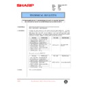
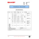
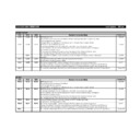
Code
Function (Purpose)
Main
Sub
46
11
Used to adjust the print density for each density level
(display value) in the copy mode (binary - photo mode).
An arbitrary print density can be set for each density level
(display value).
(display value) in the copy mode (binary - photo mode).
An arbitrary print density can be set for each density level
(display value).
12
Used to adjust the print density in the FAXmode (all
modes).
The print densities in all the modes (all the specified
levels set for all the density levels (display values)) can be
collectively adjusted. (Same as SIM 46-13A.) (FAX model
only)
modes).
The print densities in all the modes (all the specified
levels set for all the density levels (display values)) can be
collectively adjusted. (Same as SIM 46-13A.) (FAX model
only)
13
Used to adjust the print density in the FAX mode (normal
character mode).
(SIM 46-13A is same as SIM 46-12.)
(FAX model only)
character mode).
(SIM 46-13A is same as SIM 46-12.)
(FAX model only)
14
Used to adjust the print density in the FAX mode (small
character modes). (FAX model only)
character modes). (FAX model only)
15
Used to adjust the print density in the FAX mode (fine
modes). (FAX model only)
modes). (FAX model only)
16
Used to adjust the print density in the FAX mode (ultra
fine modes). (FAX model only)
fine modes). (FAX model only)
17
Used to execute shading correction and display the
correction value.
correction value.
18
Used to adjust
γ
(density gradient) in each copy mode.
(Target models: AR-2X1/3X1/4XX/250/XX6 series)
19
Used to adjust
γ
(density gradient) and set the density
detection area in the auto copy mode and to set the
image process mode in the photo copy mode. (Target
models: AR-2X1/3X1/4XX/250/XX6 series)
image process mode in the photo copy mode. (Target
models: AR-2X1/3X1/4XX/250/XX6 series)
20
Used to adjust the copy density correction in the SPF
copy mode for the document table copy mode. Adjustment
is made so that the copy density is the same as that in
the document table copy mode. (Target models:
AR-2X1/3X1/4XX/250/XX6 series)
copy mode for the document table copy mode. Adjustment
is made so that the copy density is the same as that in
the document table copy mode. (Target models:
AR-2X1/3X1/4XX/250/XX6 series)
48
1
Used to adjust the copy magnification ratio (main scanning
direction, sub scanning direction).
direction, sub scanning direction).
50
1
Used to adjust the copy image position and the void area
(image loss) on the print paper in the copy mode. (The
same adjustment can be made with SIM 50-2 (simple
method).)
(image loss) on the print paper in the copy mode. (The
same adjustment can be made with SIM 50-2 (simple
method).)
2
Used to adjust the copy image position and the void area
(image loss) on the print paper in the copy mode. (Simple
adjustment)
(This simulation allows the same simulation with SIM 50-1
more simply. )
(image loss) on the print paper in the copy mode. (Simple
adjustment)
(This simulation allows the same simulation with SIM 50-1
more simply. )
5
Used to adjust the print image position (top margin) on the
print paper in the print mode.
print paper in the print mode.
10
Used to adjust the print image center position. (Adjustment
can be made for each paper feed section.)
can be made for each paper feed section.)
12
Used to adjust the print image center position. (Adjustment
can be made for each document mode.)
can be made for each document mode.)
51
1
Used to adjust the OPC drum separation pawl ON timing.
2
Used to adjust the contact pressure of paper onto the
resist roller in each section (copier paper feed section,
duplex paper feed section, SPF paper feed section).
(When the print image position varies greatly for the paper
or when a lot of paper jam troubles occur, the adjustment
is required.)
resist roller in each section (copier paper feed section,
duplex paper feed section, SPF paper feed section).
(When the print image position varies greatly for the paper
or when a lot of paper jam troubles occur, the adjustment
is required.)
52
1
Used to adjust the duplex print mode stacking capability.
(Used to adjust the stop position of the paper tray width
direction alignment plate in the duplex unit. The
adjustment is executed by changing the width direction
alignment plate home position inthe software.)
(Used to adjust the stop position of the paper tray width
direction alignment plate in the duplex unit. The
adjustment is executed by changing the width direction
alignment plate home position inthe software.)
53
1
Used to adjust the document stop position in each
operation mode of ADF/RADF. (Target model:
AR-F230/S280/F280R/S330/280/285/335)
operation mode of ADF/RADF. (Target model:
AR-F230/S280/F280R/S330/280/285/335)
2
Used to adjust the optical sensor sensitivity in the
ADF/RADF. (Target models:
AR-F230/S280/F280R/S330/280/285/335)
ADF/RADF. (Target models:
AR-F230/S280/F280R/S330/280/285/335)
60
1
Used to check the operation (read/write) of ICU (DRAM).
(SIMM MEMORY/ONBOARD MEMORY)
(SIMM MEMORY/ONBOARD MEMORY)
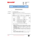
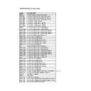
Code
Function (Purpose)
Main
Sub
61
1
Used to test the operation of the scanner (exposure) unit.
2
Used to adjust the scanner (exposure) laser power
(absolute value) in the copy mode.
(absolute value) in the copy mode.
3
Used to adjust the scanner (exposure) laser power
(absolute value) in the FAX (auto) mode. (FAX model
only)
(absolute value) in the FAX (auto) mode. (FAX model
only)
4
Used to adjust the scanner (exposure) laser power
(absolute value) in the printer mode. (For Photoconductor
type B)
(absolute value) in the printer mode. (For Photoconductor
type B)
62
1
Used to format the hard disk. (Target models:
AR-S330/280/285/335)(Models with the hard disk installed
only)
AR-S330/280/285/335)(Models with the hard disk installed
only)
2
Used to check the operation (read/write) of the hard disk.
(Target models: AR-S330/280/285/335)(Models with the
hard disk installed only.) (Partial check)
(Target models: AR-S330/280/285/335)(Models with the
hard disk installed only.) (Partial check)
3
Used to check the operation (read/write) of the hard disk.
(Target models: AR-S330/280/285/335) (Only the models
with a hard disk) (All area check)
(Target models: AR-S330/280/285/335) (Only the models
with a hard disk) (All area check)
63
1
Used to check the result of shading correction. (The
shading correctiondata are displayed.)
shading correctiondata are displayed.)
64
1
Used to check the operation of the printer function (auto
print operation). (Print pattern, paper feed mode, print
mode, the number of sheets, and the density can be set
to an arbitrary value.)
print operation). (Print pattern, paper feed mode, print
mode, the number of sheets, and the density can be set
to an arbitrary value.)
65
1
Used to adjust the touch panel (LCD display) detecting
position.
position.
2
Used to check the result of the touch panel (LCD display)
detecting position adjustment. (The coordinates are
displayed.)
detecting position adjustment. (The coordinates are
displayed.)
66
35
Used to check the communication test between the FAX
main PWB and the sub PWB. (FAX model only)
main PWB and the sub PWB. (FAX model only)
36
Used to check the FAX sub PWB memory operation
(read/write). (When replacing the PWB with a new one,
this check must be performed.)(FAX model only)
(read/write). (When replacing the PWB with a new one,
this check must be performed.)(FAX model only)
67
1
Used to check the printer PWB memory operation
(read/write). (When replacing the PWB with a new one,
this check must be performed.)
(read/write). (When replacing the PWB with a new one,
this check must be performed.)
2
Used to check the printer parallel I/F operation. (This
simulation is used only for production, and a special tool
is required. Not available in the market.)
simulation is used only for production, and a special tool
is required. Not available in the market.)
3
Used to adjust the printer parallel I/F ACk signal width.
11
Used to set YES/NO of the printer parallel I/F SELECT IN
signal.
signal.
12
Used to write data into the printer flash memory.
13
Used to check the printer flash memory data.
14
Used to check the printer flash memory data writing and
its result.
its result.
15
Used to check the sum of the printer flash memory.
16
Used to check the operation of the network card.
17
Used to clear data in the NVRAM of the printer PWB (set
to the default). (Printer set data)
to the default). (Printer set data)
68
1
Used to check the operation of infrared communication I/F
(Zaurus link) and the related circuit. (Target models:
AR-F230/S280/F280S/F280R/S330)(Japan models only)
(Zaurus link) and the related circuit. (Target models:
AR-F230/S280/F280S/F280R/S330)(Japan models only)
AR-405
8 – 5
1/21/1999
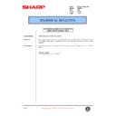
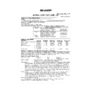
C. Details of simulations
1
1 - 1
Purpose
Operation test/check
Function
(Purpose)
(Purpose)
Used to check the operation of the scanner unit and its control circuit.
Section
Optical (Image scanning)
Item
Operation
Operation/
Procedure
Procedure
1. Select the copy (scanning) magnification ratio with the zoom key.
The magnification ratio can be increased or decreased with the [ZOOM] key by the increment of 1%.
The selected magnification ratio is displayed on the magnification ratio display.
The selected magnification ratio is displayed on the magnification ratio display.
2. Press the [EXECUTE] key.
Scanning is performed at the magnification ratio set in procedure 1 is executed. During scanning, the [EXECUTE] key
is highlighted.
If the [EXECUTE] key is pressed under this state, the operation is interrupted. After completion of scanning, the
[EXECUTE] key returns to the normal display.
is highlighted.
If the [EXECUTE] key is pressed under this state, the operation is interrupted. After completion of scanning, the
[EXECUTE] key returns to the normal display.
To resume scanning, start with procedure 2.
To change the magnification ratio, start with procedure 1.
Scanning is performed at the max. scanning length (432mm). If, however, the magnification ratio is set to greater than
100%, the scanning length is changed accordingly.
To change the magnification ratio, start with procedure 1.
Scanning is performed at the max. scanning length (432mm). If, however, the magnification ratio is set to greater than
100%, the scanning length is changed accordingly.
Note
1 - 2
Purpose
Operation test/check
Function
(Purpose)
(Purpose)
Used to check the operatioin of sensors and detectors in the scanner section and the related circuit.
Section
Optical (Image scanning)
Item
Operation
Operation/
Procedure
Procedure
The operations of sensors and detectors in the scanner section are displayed.
The active sensors and detectors are highlighted.
The active sensors and detectors are highlighted.
Note
AR-405
1/21/1999
8 – 6
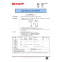
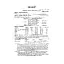
2
2 - 1
Purpose
Operation test/check
Function
(Purpose)
(Purpose)
Used to check the operation of the RADF unit and its control circuit.
Section
ADF/RADF/UDH/SPF
Item
Operation
Operation/
Procedure
Procedure
1. Select the aging mode with the key.
When selection is made, the selected item is highlighted.
[1:SIDE]: Single copy aging mode
[2:SIDE] Duplex copy aging mode
[1:SIDE]: Single copy aging mode
[2:SIDE] Duplex copy aging mode
(Note) [2:SIDE] is displayed only when the unit which allows duplex copy is installed.
2. Select the copy magnification ratio with the key.
(The magnification ratio can be increased or decreased in the increment of 1% with the [ZOOM] key.)
The selected magnification ratio is displayed on the magnification ratio display on the screen.
The magnification ratio can be set only when SPF is installed.
The magnification ratio can be set only when SPF is installed.
3. Press the [EXECUTE] key.
Aging of the document feeder is executed under the conditions specified with procedures 1 and 2.
During aging, the [EXECUTE] key is highlighted. If the [EXECUTE] key is pressed while it is highlighted, the operation
is interrupted.
When two or more operations are selected in procedure 1, "1:SIDE" (single copy aging mode) is unconditionally
performed and the other highlighted displays return to the normal display.
To resume aging, execute with procedure 3.
To change the conditions for aging, execute with procedure 1.
*
When the SPF is installed , the magnification ratio can be adjusted in the range of 64% - 200%.
Note
2 - 2
Purpose
Operation test/check
Function
(Purpose)
(Purpose)
Used to check the operation of sensors and detectors in the RADF units and the related circuit.
Section
ADF/RADF/UDH/SPF
Item
Operation
Operation/
Procedure
Procedure
The operations of sensors and detectors in the RADF/ADF/SPFsection are displayed.
The active sensors and detectors are highlighted.
[ADF/RADF installed]
DSS
Empty sensor
Normal display: Document empty
Highlighted: display: Document exist
DFD
Resist sensor
Normal display: Document empty
Highlighted display: Document exist
DTD
Paper timing sensor
Normal display: Document empty
Highlighted display: Document exist
AUOD
DF open/close sensor
Normal display: Close
Highlighted display: Open
TSS1
Tray feed size sensor (large size)
Normal display: Document empty
Highlighted display: Document exist
TSS2
Tray feed size sensor (small size)
Normal display: Document empty
Highlighted display: Document exist
DWS1
Tray width sensor (182mm)
Normal display: OFF
Highlighted display: ON
DWS2
Tray width senso
(210mm/215.9mm)
(210mm/215.9mm)
Normal display: OFF
Highlighted display: ON
DWS3
Tray width sensor (257mm)
Normal display: OFF
Highlighted display: ON
DWS4
Tray width sensor (279.4mm)
Normal display: OFF
Highlighted display: ON
DWS5
Tray width sensor (297mm)
Normal display: OFF
Highlighted display: ON
RDD
Paper exit sensor
Normal display: OFF
Highlighted display: ON
AR-405
8 – 7
1/21/1999
[SPF installed]
DSS empty sensor
Normal display: Document empty
Highlighted display: Document exist
DFD resist sensor
Normal display: Document empty
Highlighted display: Document exist
RDD paper exit sensor
Normal display: Document empty
Highlighted display: Document exist
AUOD DF open/close sensor
Normal display: Close
Highlighted display: Open
TSS1 tray feed size sensor (large size)
Normal display: Document empty
Highlighted display: Document exist
TSS2 tray feed size sensor (small size)
Normal display: Document empty
Highlighted display: Document exist
DWS1 tray width sensor (182mm)
Normal display: OFF
Highlighted display: ON
DWS2 tray width sensor
(210mm/215.9mm)
(210mm/215.9mm)
Normal display: OFF
Highlighted display: ON
DWS3 tray width sensor (257mm)
Normal display: OFF
Highlighted display: ON
DWS4 tray width sensor (279.4mm)
Normal display: OFF
Highlighted display: ON
DWS5 tray width sensor (297mm)
Normal display: OFF
Highlighted display: ON
Note
2 - 3
Purpose
Operation test/check
Function
(Purpose)
(Purpose)
Used to check the operation of the loads in the RADF/ADF/SPF units and the control circuits.
Section
ADF/RADF/UDH/SPF
Item
Operation
Operation/
Procedure
Procedure
1. The names of the loads which can be operated are displayed. Select the load to be checked with the key, and the
selected load is highlighted.
2. Press the [EXECUTE] key.
The load selected in procedure 1 starts the operation. During the operation of the load, the [EXECUTE] key is
highlighted. If the EXECUTE key is pressed while it is highlighted, the operation is stopped.
When two or more operations are selected in procedure 1, the operation is performed in the sequence of display
order.
highlighted. If the EXECUTE key is pressed while it is highlighted, the operation is stopped.
When two or more operations are selected in procedure 1, the operation is performed in the sequence of display
order.
[When ADF/RADF is installed]
DFM
FORWORD Paper feed motor forward rotation
DFM
REVERSE Paper feed motor reverse rotation
DTM
FORWORD Transport motor forward rotation
DTM
REVERSE Transport motor reverse rotation
DRM
Paper expulsion motor
DFSOL
Paper feed solenoid
[When SPF is installed]
DTM
FORWORD Transport motor forward rotation
DTM
REVERSE
Transport motor reverse rotation
STAMP
SOL
Stamp solenoid
Note
AR-405
1/21/1999
8 – 8

