Sharp AR-285 (serv.man15) Service Manual ▷ View online
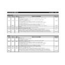
Trouble code
Description
Main
code
code
Sub
code
U6
01
∼
02
Content Desk 1, 2 CS lift-up trouble
Detail
Desk cassette lift-up trouble (1st - 3rd
cassettes).
cassettes).
Cause
Defective sensor
RADF control PWB defective
Broken gear
Lift-up motor defective
RADF control PWB defective
Broken gear
Lift-up motor defective
Check
and
remedy
and
remedy
Check lift-up sensor detection with
SIM4-2.
Check lift-up motor with SIM4-3.
SIM4-2.
Check lift-up motor with SIM4-3.
08
Content Desk 24-V power supply error
Detail
No supply of DC24V to desk
Cause
Improper connection or broken wire of
connector or harness
Desk control PWB defective
Power supply unit defective
connector or harness
Desk control PWB defective
Power supply unit defective
Check
and
remedy
and
remedy
Check power supply line connector and
harness.
Check 24-V voltage on power supply unit
and desk control PWB.
harness.
Check 24-V voltage on power supply unit
and desk control PWB.
09
Content LCC lift motor trouble
Detail
LCC lift motor trouble
Cause
Sensor trouble
LCC control PWB trouble
Gear breakage
Lift motor trouble
LCC control PWB trouble
Gear breakage
Lift motor trouble
Check
and
remedy
and
remedy
Check the sensor detection with SIM 4-2.
Check the lift motor operation with SIM
4-3.
Check the lift motor operation with SIM
4-3.
10
Content Desk transport motor trouble
Detail
Desk transport motor operation trouble
Cause
Motor lock
Improper motor speed
Overcurrent to motor
RADF control PWB defective
Improper motor speed
Overcurrent to motor
RADF control PWB defective
Check
and
remedy
and
remedy
Check transport motor operation with
SIM4-6.
SIM4-6.
20
Content LCC communication trouble
Detail
LCC communication trouble
Error when power is turned on or in
communication line test after exiting SIM.
Error when power is turned on or in
communication line test after exiting SIM.
Cause
Connector harness improper connection
or disconnection
LCC control PWB trouble
Control PWB (PCU) trouble
Malfunction by noise
or disconnection
LCC control PWB trouble
Control PWB (PCU) trouble
Malfunction by noise
Check
and
remedy
and
remedy
Canceled by turning on the power.
Check the connector and harness of the
communication line.
Check the connector and harness of the
communication line.
21
Content LCC transport motor trouble
Detail
LCC transport motor operation trouble
Cause
Motor lock
Motor rpm abnormality
Motor overcurrent
LCC control PWB trouble
Motor rpm abnormality
Motor overcurrent
LCC control PWB trouble
Check
and
remedy
and
remedy
Check the transport motor operation with
SIM 4-3.
SIM 4-3.
Trouble code
Description
Main
code
code
Sub
code
U6
22
Content LCC 24V power abnormality
Detail
DC24V not supplied to LCC
Cause
Connector harness improper connection
or disconnection
LCC control PWB trouble
Power unit trouble
or disconnection
LCC control PWB trouble
Power unit trouble
Check
and
remedy
and
remedy
Check the connector and harness of
power line.
Check 24V power in the power unit and
the LCC control PWB.
power line.
Check 24V power in the power unit and
the LCC control PWB.
U7
00
Content RIC communication trouble
Detail
RIC communication error
Error when the power is turned on or in
communication test after exiting from
SIM.
Error when the power is turned on or in
communication test after exiting from
SIM.
Cause
Connector harness improper connection
or disconnection
RIC control PWB (ICU) trouble
Malfunction by noise
or disconnection
RIC control PWB (ICU) trouble
Malfunction by noise
Check
and
remedy
and
remedy
Canceled by turning on the power.
Check the connector and harness of the
power line.
Check the connector and harness of the
power line.
PF
00
Content RIC copy inhibition signal received
Detail
Copy inhibition command received from
RIC (host)
RIC (host)
Cause
Judged by the host.
Check
and
remedy
and
remedy
Notice to the host
EE
EL
Content Auto developing tone adjustment trouble
(overtoner error)
Detail
A sample data is less than 0 when auto
developing adjustment is executed.
developing adjustment is executed.
Cause
Toner density sensor defective
Charging voltage or developing voltage
improper.
Toner density improper
Developing unit defective
PCU PWB defective
Charging voltage or developing voltage
improper.
Toner density improper
Developing unit defective
PCU PWB defective
Check
and
remedy
and
remedy
Make auto developing adjustment with
SIM25-2.
SIM25-2.
EU
Content Auto developing adjustment trouble
(undertoner error)
Detail
A sample data is less than 99 when auto
developing adjustment is executed.
developing adjustment is executed.
Cause
Toner density sensor defective
Charging voltage or developing voltage
improper
Toner density improper
Unit defective
PCU PWB defective
Charging voltage or developing voltage
improper
Toner density improper
Unit defective
PCU PWB defective
Check
and
remedy
and
remedy
Make auto developing adjustment with
SIM25-2.
SIM25-2.
PF
00
Content RIC copy inhibition signal received
Detail
Copy inhibition command received from
the host (RIC)
the host (RIC)
Cause
Judged by the host
Check
and
remedy
and
remedy
Notice to the host
11 – 7
Trouble code
Description
Main
code
code
Sub
code
U9
E7
E7
F9
00
Content U9–
: ICU-OPE communication
trouble (ICU detection)
E7–
E7–
: ICU-PCU communication
trouble (ICU detection)
F9–
F9–
: ICU-PRT communication
trouble (ICU detection)
Detail
Communication setup error,
framing/parity/protocol error
framing/parity/protocol error
Cause
Slave unit PWB connector improper
connection
Slave unit PWB – ICU PWB harness
trouble
Connector pin breakage of the motor
PWB of the slave unit PWB
Slave unit ROM trouble. no ROM, ROM
reverse insertion, ROM pin breakage
connection
Slave unit PWB – ICU PWB harness
trouble
Connector pin breakage of the motor
PWB of the slave unit PWB
Slave unit ROM trouble. no ROM, ROM
reverse insertion, ROM pin breakage
Check
and
remedy
and
remedy
Connect the connector of the slave unit
PWB and the ICU PWB.
Check the connection and the harness.
Check the grounding of the copier.
Check the ROM of the slave unit PWB.
PWB and the ICU PWB.
Check the connection and the harness.
Check the grounding of the copier.
Check the ROM of the slave unit PWB.
90
Content U9–
: ICU-OPE communication
trouble (OPE detection)
E7–
E7–
: ICU-PCU communication
trouble (PCU detection)
F9–
F9–
: ICU-PRT communication
trouble (PRT detection)
Detail
Communication setup
error/framing/parity/protocol error
error/framing/parity/protocol error
Cause
Slave unit PWB connector improper
connection
Slave unit PWB – ICU PWB harness
trouble
Slave unit PWB mother board connector
pin breakage
connection
Slave unit PWB – ICU PWB harness
trouble
Slave unit PWB mother board connector
pin breakage
Check
and
remedy
and
remedy
Check the slave unit PWB and the ICU
PWB connector connection and
connection.
Check the copier earth.
PWB connector connection and
connection.
Check the copier earth.
F9
01
Content PRT DRAM trouble
Detail
Option printer PWB DRAM trouble
(Check when turning on the power.)
(Check when turning on the power.)
Cause
DRAM module is broken and access
cannot be made.
DRAM module improper installation
cannot be made.
DRAM module improper installation
Check
and
remedy
and
remedy
Check with SIM 67-1.
U2
00
Content EEPROM read/write error
Detail
EEPRO version error. Error in writing into
EEPROM.
EEPROM.
Cause
EEPROM defective
Uninitialized EEPROM is installed
Defective EEPROM access circuit on
PCU PWB
Uninitialized EEPROM is installed
Defective EEPROM access circuit on
PCU PWB
Check
and
remedy
and
remedy
Check EEPROM for proper set-up
To prevent the erasion of counter data
and adjustment values, write down the
counter data and adjustment values by
simulation. (If there is a printer option,
execute SIM23-1 and note counter
data/adjustment values.)
Clear U2 trouble with SIM16.
Replace PCU PWB.
To prevent the erasion of counter data
and adjustment values, write down the
counter data and adjustment values by
simulation. (If there is a printer option,
execute SIM23-1 and note counter
data/adjustment values.)
Clear U2 trouble with SIM16.
Replace PCU PWB.
Trouble code
Description
Main
code
code
Sub
code
U2
11
Content Counter checksum error
Detail
Checksum error in counter data area
Cause
EEPROM defective
Control circuit hung up due to noise
Defective EEPROM access circuit on
PCU PWB
Control circuit hung up due to noise
Defective EEPROM access circuit on
PCU PWB
Check
and
remedy
and
remedy
Check EEPROM for proper set-up
To prevent the erasion of counter data
and adjustment values, write down the
counter data and adjustment values by
simulation. (If there is a printer option,
execute SIM23-1 and note counter
data/adjustment values.)
Clear U2 trouble with SIM16.
Replace PCU PWB.
To prevent the erasion of counter data
and adjustment values, write down the
counter data and adjustment values by
simulation. (If there is a printer option,
execute SIM23-1 and note counter
data/adjustment values.)
Clear U2 trouble with SIM16.
Replace PCU PWB.
12
Content Adjustment value checksum error
Detail
Checksum error in adjustment value data
area
area
Cause
EEPROM defective
Control circuit hung up due to noise.
Defective EEPROM access circuit on
PCU PWB
Control circuit hung up due to noise.
Defective EEPROM access circuit on
PCU PWB
Check
and
remedy
and
remedy
Check EEPROM for proper set-up
To prevent the erasion of counter data
and adjustment values, write down the
counter data and adjustment values by
simulation. (If there is a printer option,
execute SIM23-1 and note counter
data/adjustment values.)
Clear U2 trouble with SIM16.
Replace PCU PWB.
To prevent the erasion of counter data
and adjustment values, write down the
counter data and adjustment values by
simulation. (If there is a printer option,
execute SIM23-1 and note counter
data/adjustment values.)
Clear U2 trouble with SIM16.
Replace PCU PWB.
11 – 8
Trouble code
Description
Main
code
code
Sub
code
U9
E7
E7
F9
00
Content U9–
: ICU-OPE communication
trouble (ICU detection)
E7–
E7–
: ICU-PCU communication
trouble (ICU detection)
F9–
F9–
: ICU-PRT communication
trouble (ICU detection)
Detail
Communication setup error,
framing/parity/protocol error
framing/parity/protocol error
Cause
Slave unit PWB connector improper
connection
Slave unit PWB – ICU PWB harness
trouble
Connector pin breakage of the motor
PWB of the slave unit PWB
Slave unit ROM trouble. no ROM, ROM
reverse insertion, ROM pin breakage
connection
Slave unit PWB – ICU PWB harness
trouble
Connector pin breakage of the motor
PWB of the slave unit PWB
Slave unit ROM trouble. no ROM, ROM
reverse insertion, ROM pin breakage
Check
and
remedy
and
remedy
Connect the connector of the slave unit
PWB and the ICU PWB.
Check the connection and the harness.
Check the grounding of the copier.
Check the ROM of the slave unit PWB.
PWB and the ICU PWB.
Check the connection and the harness.
Check the grounding of the copier.
Check the ROM of the slave unit PWB.
90
Content U9–
: ICU-OPE communication
trouble (OPE detection)
E7–
E7–
: ICU-PCU communication
trouble (PCU detection)
F9–
F9–
: ICU-PRT communication
trouble (PRT detection)
Detail
Communication setup
error/framing/parity/protocol error
error/framing/parity/protocol error
Cause
Slave unit PWB connector improper
connection
Slave unit PWB – ICU PWB harness
trouble
Slave unit PWB mother board connector
pin breakage
connection
Slave unit PWB – ICU PWB harness
trouble
Slave unit PWB mother board connector
pin breakage
Check
and
remedy
and
remedy
Check the slave unit PWB and the ICU
PWB connector connection and
connection.
Check the copier earth.
PWB connector connection and
connection.
Check the copier earth.
F9
01
Content PRT DRAM trouble
Detail
Option printer PWB DRAM trouble
(Check when turning on the power.)
(Check when turning on the power.)
Cause
DRAM module is broken and access
cannot be made.
DRAM module improper installation
cannot be made.
DRAM module improper installation
Check
and
remedy
and
remedy
Check with SIM 67-1.
U2
00
Content EEPROM read/write error
Detail
EEPRO version error. Error in writing into
EEPROM.
EEPROM.
Cause
EEPROM defective
Uninitialized EEPROM is installed
Defective EEPROM access circuit on
PCU PWB
Uninitialized EEPROM is installed
Defective EEPROM access circuit on
PCU PWB
Check
and
remedy
and
remedy
Check EEPROM for proper set-up
To prevent the erasion of counter data
and adjustment values, write down the
counter data and adjustment values by
simulation. (If there is a printer option,
execute SIM23-1 and note counter
data/adjustment values.)
Clear U2 trouble with SIM16.
Replace PCU PWB.
To prevent the erasion of counter data
and adjustment values, write down the
counter data and adjustment values by
simulation. (If there is a printer option,
execute SIM23-1 and note counter
data/adjustment values.)
Clear U2 trouble with SIM16.
Replace PCU PWB.
Trouble code
Description
Main
code
code
Sub
code
U2
11
Content Counter checksum error
Detail
Checksum error in counter data area
Cause
EEPROM defective
Control circuit hung up due to noise
Defective EEPROM access circuit on
PCU PWB
Control circuit hung up due to noise
Defective EEPROM access circuit on
PCU PWB
Check
and
remedy
and
remedy
Check EEPROM for proper set-up
To prevent the erasion of counter data
and adjustment values, write down the
counter data and adjustment values by
simulation. (If there is a printer option,
execute SIM23-1 and note counter
data/adjustment values.)
Clear U2 trouble with SIM16.
Replace PCU PWB.
To prevent the erasion of counter data
and adjustment values, write down the
counter data and adjustment values by
simulation. (If there is a printer option,
execute SIM23-1 and note counter
data/adjustment values.)
Clear U2 trouble with SIM16.
Replace PCU PWB.
12
Content Adjustment value checksum error
Detail
Checksum error in adjustment value data
area
area
Cause
EEPROM defective
Control circuit hung up due to noise.
Defective EEPROM access circuit on
PCU PWB
Control circuit hung up due to noise.
Defective EEPROM access circuit on
PCU PWB
Check
and
remedy
and
remedy
Check EEPROM for proper set-up
To prevent the erasion of counter data
and adjustment values, write down the
counter data and adjustment values by
simulation. (If there is a printer option,
execute SIM23-1 and note counter
data/adjustment values.)
Clear U2 trouble with SIM16.
Replace PCU PWB.
To prevent the erasion of counter data
and adjustment values, write down the
counter data and adjustment values by
simulation. (If there is a printer option,
execute SIM23-1 and note counter
data/adjustment values.)
Clear U2 trouble with SIM16.
Replace PCU PWB.
11 – 8

