|
|
AR-285 (serv.man5)
AR280 285 335 Service Manual-General
Service Manual
|
6
|
187.54 KB
|
|
|
AR-285 (serv.man6)
AR280 285 335 Service Manual-Specifications
Service Manual
|
7
|
82.25 KB
|
|
|
AR-285 (serv.man7)
AR280 285 335 Service Manual-Options
Service Manual
|
5
|
56.11 KB
|
|
|
AR-285 (serv.man8)
AR280 285 335 Service Manual-Consumable Parts
Service Manual
|
8
|
82.97 KB
|
|
|
AR-285 (serv.man9)
AR280 285 335 Service Manual-Installation and Set Up
Service Manual
|
12
|
552.83 KB
|
|
|
AR-285 (serv.man10)
AR280 285 335 Service Manual-External View and Internal Structure
Service Manual
|
11
|
546.8 KB
|
|
|
AR-285 (serv.man12)
AR280 285 335 Service Manual-Simulation Codes
Service Manual
|
118
|
877.93 KB
|
|
|
AR-285 (serv.man13)
AR280 285 335 Service Manual-Maintenance
Service Manual
|
25
|
2.97 MB
|
|
|
AR-285 (serv.man14)
AR280 285 335 Service Manual-Disassembly and Assembly
Service Manual
|
20
|
1.99 MB
|
|
|
AR-285 (serv.man15)
AR280 285 335 Service Manual-Trouble Code List
Service Manual
|
10
|
81.02 KB
|
|
|
AR-285 (serv.man16)
AR280 285 335 Service Manual-Operational Description
Service Manual
|
6
|
59.52 KB
|
|
|
AR-285 (serv.man17)
AR280 285 335 Circuit PWB Location
Service Manual
|
2
|
76.34 KB
|
|
|
AR-285 (serv.man18)
AR280 285 335 Circuit Wiring Chart
Service Manual
|
8
|
162 KB
|
|
|
AR-285 (serv.man19)
AR280 285 335 Circuit ICU PWB
Service Manual
|
16
|
558.48 KB
|
|
|
AR-285 (serv.man20)
AR280 285 335 Circuit PCU PWB
Service Manual
|
7
|
281.94 KB
|
|
|
AR-285 (serv.man21)
AR280 285 335 Circuit Operation Control PWB
Service Manual
|
6
|
252.56 KB
|
|
|
AR-285 (serv.man22)
AR280 285 335 Circuit Operation L R PWB
Service Manual
|
2
|
59.31 KB
|
|
|
AR-285 (serv.man23)
AR280 285 335 Circuit AC DC Power Supply
Service Manual
|
5
|
146.11 KB
|
|
|
AR-285 (serv.man24)
AR280 285 335 Circuit DC Power Supply
Service Manual
|
3
|
298.34 KB
|
|
|
AR-285 (serv.man25)
AR280 285 335 Circuit SPF
Service Manual
|
3
|
155.18 KB
|
|
|
AR-285 (serv.man26)
AR280 285 335 Circuit RADF
Service Manual
|
4
|
111.27 KB
|
|
|
AR-285 (serv.man34)
AR280 285 335 Operation Manual-Section 1
User Manual / Operation Manual
|
78
|
1.68 MB
|
|
|
AR-285 (serv.man35)
AR280 285 335 Operation Manual-Section 2
User Manual / Operation Manual
|
58
|
1.49 MB
|
|
|
AR-285 (serv.man36)
AR280 285 335 Operation Manuals-Section 3
User Manual / Operation Manual
|
32
|
184.36 KB
|
|
|
AR-285 (serv.man27)
Information of parts change
Service Manual / Parts Guide
|
2
|
28.25 KB
|
|
|
AR-285 (serv.man28)
Parts Guide AR250 280 285 287 335 337 405 407 505 507
Service Manual / Parts Guide
|
127
|
5.15 MB
|
|
|
AR-285 (serv.man29)
AR280 285 335 Parts Guide-Exteriors Operation panel unit Document size sensor unit Optical unit 1 Optical unit 2 Copy lamp unit 2nd,3rd mirror holder unit Frame section Rear frame 1
Service Manual / Parts Guide
|
15
|
1.79 MB
|
|
|
AR-285 (serv.man30)
AR280 285 335 Parts Guide-Rear frame 2 Photo conductor unit Tonor hopper unit Developer unit Fusing unit 1 Fusing unit 2 2 bin delivery turnover unit 1 2 bin delivery turnover unit 2 Vertical transport right door unit
Service Manual / Parts Guide
|
19
|
1.73 MB
|
|
|
AR-285 (serv.man31)
AR280 285 335 Parts Guide-Vertical transport unit PS transport unit Suction unit Main drive unit1 Main drive unit2 Paper feeding drive unit1 Paper feeding drive unit2 DV drive unit Fusing drive unit DV guide unit
Service Manual / Parts Guide
|
17
|
1.5 MB
|
|
|
AR-285 (serv.man32)
AR280 285 335 Parts Guide-Multi manual paper feeding unit1 Multi manual paper feeding unit2 Waste toner unit Tray paper feeding tray unit Multi manual paper feeding tray unit MC Unit TC Unit Tray Unit Packing material accessories
Service Manual / Parts Guide
|
17
|
1.17 MB
|
|
|
AR-285 (serv.man33)
AR280 285 335 Parts Guide-PCU PWB ICU PWB Operation control PWB Operation PWB R Operation PWB L Inverter PWB AC PWB Scanner drive PWB ORS PD PWB DC Power supply PWB
Service Manual / Parts Guide
|
25
|
393.49 KB
|
|
|
AR-285 (serv.man4)
AR280,285,335 Specifications
Service Manual / Specification
|
5
|
82.97 KB
|
|
|
AR-285 (serv.man44)
Change of Fuser Cover Part Number.
Service Manual / Technical Bulletin
|
1
|
25.47 KB
|
|
|
AR-285 (serv.man45)
Improvement made to prevent fire hazard caused by imperfect contact on fixing junction PWB.
Service Manual / Technical Bulletin
|
1
|
45.23 KB
|
|
|
AR-285 (serv.man46)
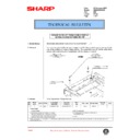
Re issue bulletin regarding a parts change - mainly for the mirror mount fixing plate.
Service Manual / Technical Bulletin
|
4
|
1.6 MB
|
|
|
AR-285 (serv.man47)
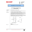
Change to the paper feed roller material.
Service Manual / Technical Bulletin
|
13
|
1.22 MB
|
|
|
AR-285 (serv.man48)
IMPROVEMENT MADE TO PREVENT MALFUNCTION CAUSED BY IMPERFECT CONTACT ON FIXING JUNCTION PWB.
Service Manual / Technical Bulletin
|
1
|
106.03 KB
|
|
|
AR-285 (serv.man49)
Reduction of F2-00 error. (Toner supply error)
Service Manual / Technical Bulletin
|
2
|
12.35 KB
|
|
|
AR-285 (serv.man50)
New service part for repairing a broken ADU frame
Service Manual / Technical Bulletin
|
2
|
239.04 KB
|
|
|
AR-285 (serv.man51)
Parts change information
Service Manual / Technical Bulletin
|
2
|
45.09 KB
|
|
|
AR-285 (serv.man52)
Paper feed drive unit part change
Service Manual / Technical Bulletin
|
1
|
30.01 KB
|
|
|
AR-285 (serv.man53)
Corrections carried out in the parts guide (DV unit toner hopper)
Service Manual / Technical Bulletin
|
2
|
91.79 KB
|
|
|
AR-285 (serv.man54)
HV protect sheet addition
Service Manual / Technical Bulletin
|
1
|
36.21 KB
|
|
|
AR-285 (serv.man55)
Corrections made to a jamming error caused by the ADU transfer clutch dragging or slipping
Service Manual / Technical Bulletin
|
1
|
42.96 KB
|
|
|
AR-285 (serv.man56)
Establishment of the paper feeding drive clutch with mylar sheet attached as a service part
Service Manual / Technical Bulletin
|
1
|
30.64 KB
|
|
|
AR-285 (serv.man57)
Parts change information
Service Manual / Technical Bulletin
|
1
|
30.58 KB
|
|
|
AR-285 (serv.man58)
Upgrade of ICU ROM version - remedy for black streaks on edge of first copy
Service Manual / Technical Bulletin
|
1
|
20.65 KB
|
|
|
AR-285 (serv.man59)
Notice of jam codes
Service Manual / Technical Bulletin
|
3
|
58.34 KB
|
|
|
AR-285 (serv.man60)
Supply of silicon oil used for cleaning the SPF glass to be carried out as a service part
Service Manual / Technical Bulletin
|
1
|
30.82 KB
|
|
|
AR-285 (serv.man61)
Copy paper jams caused by grease entering the internal section of the paper feeding drive clutch and supply of Hanari grease as a service part
Service Manual / Technical Bulletin
|
1
|
34.6 KB
|
|
|
AR-285 (serv.man62)
Corrections carried out in the parts guide
Service Manual / Technical Bulletin
|
1
|
30.08 KB
|
|
|
AR-285 (serv.man63)
Change carried out in the developer
Service Manual / Technical Bulletin
|
1
|
18.42 KB
|
|
|
AR-285 (serv.man64)
Change carried out in the material of the reversion gate
Service Manual / Technical Bulletin
|
1
|
29.83 KB
|
|
|
AR-285 (serv.man65)
Establishment of the CG reverse roller shaft UN and the Reverse roller shaft UN in the 550 paper feeding unit as service parts
Service Manual / Technical Bulletin
|
2
|
52.22 KB
|
|
|
AR-285 (serv.man66)
Parts change information
Service Manual / Technical Bulletin
|
4
|
140.65 KB
|
|
|
AR-285 (serv.man67)
Correction carried out in the parts guide for the charger wire
Service Manual / Technical Bulletin
|
1
|
19.24 KB
|
|
|
AR-285 (serv.man68)
Part changes
Service Manual / Technical Bulletin
|
1
|
33.24 KB
|
|
|
AR-285 (serv.man69)
Improvement of paper jam udulation caused by hardening of the delivery roller
Service Manual / Technical Bulletin
|
1
|
22.17 KB
|
|
|
AR-285 (serv.man70)
Notice of jam cause codes
Service Manual / Technical Bulletin
|
3
|
153.48 KB
|
|
|
AR-285 (serv.man71)
Providing a caution label, as a service part, on adding toner
Service Manual / Technical Bulletin
|
2
|
70.59 KB
|
|
|
AR-285 (serv.man72)
Using the same hand-feed pick-up roller as the 550 paper-feeding unit
Service Manual / Technical Bulletin
|
1
|
29.8 KB
|
|
|
AR-285 (serv.man73)
Correction to compatability fo the copy lamp unit in bulletin 009
Service Manual / Technical Bulletin
|
1
|
35.08 KB
|
|
|
AR-285 (serv.man74)
Parts change information
Service Manual / Technical Bulletin
|
1
|
30.88 KB
|
|
|
AR-285 (serv.man75)
Parts change information
Service Manual / Technical Bulletin
|
3
|
139.51 KB
|
|
|
AR-285 (serv.man76)
Polygon motors for laser units.
Service Manual / Technical Bulletin
|
1
|
20.7 KB
|
|
|
AR-285 (serv.man77)
SIMM manufacturer change.
Service Manual / Technical Bulletin
|
1
|
29.85 KB
|
|
|
AR-285 (serv.man78)
Changes to polygon motor inside LSU.
Service Manual / Technical Bulletin
|
1
|
18.99 KB
|
|
|
AR-285 (serv.man79)
Change to pulley fixing double-thread screw and discontinued M4 tap.
Service Manual / Technical Bulletin
|
1
|
86.5 KB
|
|
|
AR-285 (serv.man80)
Change carried out in the hopper seal of the developing tank.
Service Manual / Technical Bulletin
|
6
|
214.28 KB
|
|
|
AR-285 (serv.man81)
Change of parts used in 550 paper feeding unit.
Service Manual / Technical Bulletin
|
2
|
124.28 KB
|
|
|
AR-285 (serv.man82)
Problem with main drive unit paper feed clutch.
Service Manual / Technical Bulletin
|
3
|
1.18 MB
|
|
|
AR-285 (serv.man83)
Addition of explanatory label for lever operation and change of suction lift shaft.
Service Manual / Technical Bulletin
|
1
|
120.99 KB
|
|
|
AR-285 (serv.man84)
Measure to alleviate problems of disengagement of the side plate in the machine cassette unit.
Service Manual / Technical Bulletin
|
2
|
125.24 KB
|
|
|
AR-285 (serv.man85)
ICU PWB part number change.
Service Manual / Technical Bulletin
|
1
|
75.06 KB
|
|
|
AR-285 (serv.man86)
Action to alleviate problems of static electricity through the use of a plastic bag for the machine.
Service Manual / Technical Bulletin
|
1
|
73.33 KB
|
|
|
AR-285 (serv.man87)
ROM software changes.
Service Manual / Technical Bulletin
|
1
|
64.41 KB
|
|
|
AR-285 (serv.man88)
Abnormal noise from process unit.
Service Manual / Technical Bulletin
|
1
|
60.77 KB
|
|
|
AR-285 (serv.man89)
Part change information.
Service Manual / Technical Bulletin
|
2
|
160.46 KB
|
|
|
AR-285 (serv.man90)
Unification of 200V series DC power unit. (WHITE)
Service Manual / Technical Bulletin
|
2
|
91.88 KB
|
|
|
AR-285 (serv.man91)
Change of supplier for sintered bearings. (WHITE)
Service Manual / Technical Bulletin
|
4
|
188.93 KB
|
|
|
AR-285 (serv.man92)
Increase in strength of ADU frame. (WHITE)
Service Manual / Technical Bulletin
|
2
|
112.62 KB
|
|
|
AR-285 (serv.man93)
Changes to the AR505 Service Manual and addition of jam cause codes. (WHITE)
Service Manual / Technical Bulletin
|
5
|
323.76 KB
|
|
|
AR-285 (serv.man94)
Change carried out in the original document detection photo sensor. (WHITE)
Service Manual / Technical Bulletin
|
1
|
74.06 KB
|
|
|
AR-285 (serv.man95)
Change carried out in the paper feeding drive frame and the transport clutch. (WHITE)
Service Manual / Technical Bulletin
|
2
|
119.5 KB
|
|
|
AR-285 (serv.man96)
Change carried out in the PS front roller bearing. (WHITE)
Service Manual / Technical Bulletin
|
1
|
83.98 KB
|
|
|
AR-285 (serv.man97)
Change carried out in the waste toner drive gear in the main drive unit. (WHITE)
Service Manual / Technical Bulletin
|
1
|
83.62 KB
|
|
|
AR-285 (serv.man98)
Version upgrade carried out on the ROM (ROM Management No. 9). (YELLOW)
Service Manual / Technical Bulletin
|
1
|
62.25 KB
|
|
|
AR-285 (serv.man99)
Change carried out in the maker of the table glass used in the RADF. (WHITE)
Service Manual / Technical Bulletin
|
2
|
117.19 KB
|
|
|
AR-285 (serv.man100)
Action to alleviate problems of dislocation of the disjunction arm in the ADU unit. (WHITE)
Service Manual / Technical Bulletin
|
1
|
83.9 KB
|
|
|
AR-285 (serv.man101)
Change carried out in the location of production of the LCU unit. (WHITE)
Service Manual / Technical Bulletin
|
1
|
88.51 KB
|
|
|
AR-285 (serv.man102)
Version upgrade carried out on the ROM. (WHITE)
Service Manual / Technical Bulletin
|
1
|
74.53 KB
|
|
|
AR-285 (serv.man103)
Discontinuance of the adjustment plate in the CCD unit. (WHITE)
Service Manual / Technical Bulletin
|
1
|
134.34 KB
|
|
|
AR-285 (serv.man104)
Countermeasure against Z-folding and paper mis-feed. (WHITE)
Service Manual / Technical Bulletin
|
4
|
552.21 KB
|
|
|
AR-285 (serv.man105)
Change carried out in the attachment screws for the operation panel LCD. (WHITE)
Service Manual / Technical Bulletin
|
1
|
136.96 KB
|
|
|
AR-285 (serv.man106)
Change in shape of the TC holder R. (WHITE)
Service Manual / Technical Bulletin
|
1
|
121.96 KB
|
|
|
AR-285 (serv.man107)
Change carried out in the shape of the bushing and the attachment gear in the paper-feeding drive unit. (WHITE)
Service Manual / Technical Bulletin
|
2
|
138.29 KB
|
|
|
AR-285 (serv.man108)
Discontinuance of the adjustment plate in the CCD unit. (WHITE)
Service Manual / Technical Bulletin
|
1
|
140.49 KB
|
|
|
AR-285 (serv.man109)
Report of flash memory version method. (WHITE)
Service Manual / Technical Bulletin
|
3
|
130.78 KB
|
|
|
AR-285 (serv.man110)
Marks on rear frame of copies, ghosting on the rear frame of copies. (WHITE)
Service Manual / Technical Bulletin
|
1
|
90.27 KB
|
|
|
AR-285 (serv.man111)
Fixing ARPB2 F9 00 error messages. (WHITE)
Service Manual / Technical Bulletin
|
2
|
96.91 KB
|
|
|
AR-285 (serv.man112)
Corrections to the Service Manual. (WHITE)
Service Manual / Technical Bulletin
|
3
|
182.29 KB
|
|
|
AR-285 (serv.man113)
Change carried out in the synchronous detection PWB in the LSU. (WHITE)
Service Manual / Technical Bulletin
|
1
|
95.5 KB
|
|
|
AR-285 (serv.man114)
1.Change carried out int he stir plate of the developing tank unit. 2.Change carried out in the material used for the TX sheet in the toner hopper unit. (WHITE)
Service Manual / Technical Bulletin
|
3
|
156.9 KB
|
|
|
AR-285 (serv.man115)
This bulletin is no longer relevant to this model
Service Manual / Technical Bulletin
|
1
|
3.6 KB
|
|
|
AR-285 (serv.man116)
1.Change Carried Out In The Plastic Slider Washer In The ADU Unit. 2.Action To Alleviate Problems Of Static Electricity In The OP Control PWB Unit. (WHITE)
Service Manual / Technical Bulletin
|
2
|
158.56 KB
|
|
|
AR-285 (serv.man117)
Report Of Flash Memory Version Method. (WHITE)
Service Manual / Technical Bulletin
|
2
|
127.57 KB
|
|
|
AR-285 (serv.man118)
1.Correction Of Screws In The Scanner Unit. 2.Addition Carried Out Of A Harness Protect Sheet S. (WHITE)
Service Manual / Technical Bulletin
|
2
|
161.75 KB
|
|
|
AR-285 (serv.man119)
1.Change Of The ICU PWB Unit At EFI's Request. 2.Change Of The Touch Panel Manufacturer. 3.Change Of The Heat-resistant Clamp Fixing Screws In The Fusing Unit. 4.Change Of The Action Time Changing The ICU PWB Memory To SDRAM. (WHITE)
Service Manual / Technical Bulletin
|
3
|
87.23 KB
|
|
|
AR-285 (serv.man120)
Extension Of The Rib On The Rail Section Of The 550-Tray Case. (WHITE)
Service Manual / Technical Bulletin
|
1
|
89.2 KB
|
|
|
AR-285 (serv.man121)
Corrections Carried Out In The Parts Guide. (WHITE)
Service Manual / Technical Bulletin
|
7
|
294.1 KB
|
|
|
AR-285 (serv.man122)
1.Screw Change. 2.Substitution For The Reflection Type Sensor. (WHITE)
Service Manual / Technical Bulletin
|
2
|
162.78 KB
|
|
|
AR-285 (serv.man123)
1.Points Of Caution To Be Observed During Maintenance Operations Of The Fusing Unit. 2.ROM Writer Functions For The ICU PWB. (WHITE)
Service Manual / Technical Bulletin
|
2
|
77.3 KB
|
|
|
AR-285 (serv.man124)
Change Carried Out In The Hard Disk. (WHITE)
Service Manual / Technical Bulletin
|
2
|
116.42 KB
|
|
|
AR-285 (serv.man125)
1.Change Carried Out In Main Harness. 2.Change Carried In The Spring Of The Multi Manual Unit. (WHITE)
Service Manual / Technical Bulletin
|
2
|
78.47 KB
|
|
|
AR-285 (serv.man126)
1.Change Carried Out In The Bearings In The Paper Feeding Drive Unit. 2.Discontinuance Of The Manual Pressure Spring Attachment Plate. (WHITE)
Service Manual / Technical Bulletin
|
2
|
79.03 KB
|
|
|
AR-285 (serv.man127)
Change Carried Out In The Shape Of The AC Harness Cover. (WHITE)
Service Manual / Technical Bulletin
|
2
|
76.15 KB
|
|
|
AR-285 (serv.man128)
Report Of Flash Memory Version Method. (WHITE)
Service Manual / Technical Bulletin
|
8
|
330.54 KB
|
|
|
AR-285 (serv.man129)
1.ICU PWB Change. 2.Shape Change Of Hard Disc Fixing Plate. (WHITE)
Service Manual / Technical Bulletin
|
2
|
96.01 KB
|
|
|
AR-285 (serv.man130)
Report Of Flash Memory Version Method. (WHITE)
Service Manual / Technical Bulletin
|
6
|
133.5 KB
|
|
|
AR-285 (serv.man131)
1.Change To The Attachment Screws Of The Optical Reception PWB Holder. 2. Measure To Alleviate Problems Of Electrical Noise In The ICU PWB. (WHITE)
Service Manual / Technical Bulletin
|
2
|
110.68 KB
|
|
|
AR-285 (serv.man132)
1.Parts Change To Incorporate Parts Manufactured By Sharp Into Assembled Units (Productivity Improvement). 2.Measure To Establish Uniformity Of The High Voltage PWB (To Improve Productivity). 3.Parts Change Carried Out In Accordance With A Change To In-house Production Of The LSU Unit. 4.Measure To Establish Uniformity Of The PCU PWB To Improve Productivity. 5.Measure To Alleviate Problems Of Scattering Of The Waste Toner. (WHITE)
Service Manual / Technical Bulletin
|
4
|
121.28 KB
|
|
|
AR-285 (serv.man133)
1.Addition Of A Distinguishing Label To The Toner Hopper Unit. 2.Change In The Shape Of The Waste Toner Drive Shaft Used In The Main Drive Unit To Improve Productivity. 3.Change To The Method Of Securing The Harness In The Paper Feeding Drive Unit. 4.Addition Of A Screw Hole In The No. 2 Bin Of The Paper Delivery Paper Guide To Improve Productivity. (WHITE)
Service Manual / Technical Bulletin
|
4
|
112.11 KB
|
|
|
AR-285 (serv.man134)
Change In The Magnetic Clutch Of The Paper Feeding Unit In The 500 Tray To Improve Productivity. (WHITE)
Service Manual / Technical Bulletin
|
2
|
103.13 KB
|
|
|
AR-285 (serv.man135)
1.Change Carried Out In The Height Of The ADU Opening And Closing PG Boss. 2.Change Carried Out In The PG Quality Of The Paper Feeding Desk. (WHITE)
Service Manual / Technical Bulletin
|
4
|
164.31 KB
|
|
|
AR-285 (serv.man136)
Establishment Of Uniformity Carried Out For The LSU Unit. (WHITE)
Service Manual / Technical Bulletin
|
1
|
38.91 KB
|
|
|
AR-285 (serv.man137)
Correction Measure Carried Out To Alleviate Problems Of Diagonal Feeding Which Occurred During Copy Operations Using The ADF. (WHITE)
Service Manual / Technical Bulletin
|
1
|
66.21 KB
|
|
|
AR-285 (serv.man138)
Measure To ALleviate Problems Of Improperly Tightened Screws In The Paper Delivery Unit. (YELLOW)
Service Manual / Technical Bulletin
|
1
|
59.97 KB
|
|
|
AR-285 (serv.man139)
1.Action Carried Out As A Measure To Improve The Precision Of The Diameter Of The PS Roller. 2.Addition Carried Out Of An Edge Guide Sheet. 3.Addition Carried Out Of A Caution Label Concerning The Laser In The LSU Unit. (WHITE)
Service Manual / Technical Bulletin
|
3
|
84.04 KB
|
|
|
AR-285 (serv.man140)
1.Change Carried Out In The Assembly Contractor Of The Toner Hopper And Developing Unit. 2.Measure Carried Out To Protect The Main Switch Harness. 3.Measure To Improve The Alignment Performance Of The Waste Toner Transport Gear. 4.Measure To Diminish Abnormal Noise Which Occurs In The Paper Delivery Reversion No.2 Bin Unit. (WHITE)
Service Manual / Technical Bulletin
|
5
|
136.78 KB
|
|
|
AR-285 (serv.man141)
Report Of Flash Memory Version Method. (WHITE)
Service Manual / Technical Bulletin
|
6
|
107.72 KB
|
|
|
AR-285 (serv.man142)
1.Discontinuance Of The Plastic Sliders Used In The Developing Unit (To Improve Productivity). 2.Establishment Of Uniformity Of The Upper Cabinet Rear (To Improve Productivity). 3.Change In The Maker Of The Drive Unit Clutch (To Improve Productivity). 4.Discontinuance Of The Boss In The Fusing Unit (To Improve Productivity). (WHITE)
Service Manual / Technical Bulletin
|
3
|
53.91 KB
|
|
|
AR-285 (serv.man143)
1.Change In The Shape Of The Attachment Plate Of The AC PWB (To Improve Productivity). 2.In-house Production Of The Operation Manuals (To Improve Productivity). (WHITE)
Service Manual / Technical Bulletin
|
2
|
45.14 KB
|
|
|
AR-285 (serv.man144)
Flash Memory - Manual Correction. (WHITE)
Service Manual / Technical Bulletin
|
5
|
164.45 KB
|
|
|
AR-285 (serv.man145)
Part Number Change - LSU Unit. (WHITE)
Service Manual / Technical Bulletin
|
1
|
40.66 KB
|
|
|
AR-285 (serv.man146)
1.Measure To Alleviate Problems Loosening Of Rubber-Leg Screws. 2.Addition Of Aluminium Tape Carried Out As A Measure To Improve Problems Of Noise. (WHITE)
Service Manual / Technical Bulletin
|
2
|
52.7 KB
|
|
|
AR-285 (serv.man147)
1.Change In The Outer Diameter Of The Paper Delivery Lock Shaft Carried Out As A Measure To Improve Productivity. 2.Measure To Alleviate Problems Of Loosening Screws Caused By Thermal Contractions. 3.Measure To Improve Problems Of Noise. (WHITE)
Service Manual / Technical Bulletin
|
4
|
85.47 KB
|
|
|
AR-285 (serv.man148)
Auditor Attachment Kit. (WHITE)
Service Manual / Technical Bulletin
|
3
|
67.76 KB
|
|
|
AR-285 (serv.man149)
E7-03 E7-11 Troubles. (WHITE)
Service Manual / Technical Bulletin
|
2
|
57.02 KB
|
|
|
AR-285 (serv.man150)
Developer Set-up Cautions. (WHITE)
Service Manual / Technical Bulletin
|
1
|
43.95 KB
|
|
|
AR-285 (serv.man151)
Parts Guide Corrections Additions. (WHITE)
Service Manual / Technical Bulletin
|
5
|
100.3 KB
|
|
|
AR-285 (serv.man152)
1.Change Carried Out In The Binding Method Of The AC Harness Line. 2.Measure To Alleviate Problems Of Screws That Do Not Fully Secure Properly. 3.Change In The 3P Terminal Base Harness Carried Out In Accordance With A Measure To Comply With EMI Standards. 4.Measure To Improve Conditions Of Noise. 5.Measure Carried Out To Prevent Contact With The ICU Cover. (WHITE)
Service Manual / Technical Bulletin
|
4
|
94.74 KB
|
|
|
AR-285 (serv.man153)
1.Change In Materials Of The PS Frame R Carried Out As A Measure To Improve Productivity. 2.Measure To Improve Paper Transport Performance When Using The RADF. 3.Measure To Aleviate Problems Of Paper Curling When Using The ADU. (WHITE)
Service Manual / Technical Bulletin
|
2
|
41.76 KB
|
|
|
AR-285 (serv.man154)
1.Addition Of Gaskets Carried Out As A Measure To Alleviate Problems Of Noise. 2.Addition Of A Ferrite Core Carried Out As A Measure To Alleviate Problems Of Noise. (WHITE)
Service Manual / Technical Bulletin
|
5
|
93.42 KB
|
|
|
AR-285 (serv.man155)
Heat Roller Wrinkling. (WHITE)
Service Manual / Technical Bulletin
|
1
|
27.17 KB
|
|
|
AR-285 (serv.man156)
1.Action To Alleviate Problems Of A Gap With The Fusing Pressure Adjustment Lever. 2.Action To Improve The Shielding Performance In The Toner Hopper Unit. 3.Measure To Alleviate Problems Of Noise In The ICU PWB. (WHITE)
Service Manual / Technical Bulletin
|
2
|
46.72 KB
|
|
|
AR-285 (serv.man157)
Labels Additions. (WHITE)
Service Manual / Technical Bulletin
|
2
|
97.72 KB
|
|
|
AR-285 (serv.man158)
1.Correction Carried Out In The Parts Guide. 2.Action To Secure Margin For The Reset Circuit. 3.Measure To Alleviate Problems OF Electronic Noise (EMI). (WHITE)
Service Manual / Technical Bulletin
|
2
|
39.35 KB
|
|
|
AR-285 (serv.man159)
Parts Guide Correction - Corrona Wire. (WHITE)
Service Manual / Technical Bulletin
|
2
|
49.7 KB
|
|
|
AR-285 (serv.man160)
Firmware Upgrade AR280 285 335, ICU3.37, OPE 3.35 and PCU 3.35 (Previously sent out as FF COP 091)
Service Manual / Technical Bulletin
|
2
|
22.6 KB
|
|
|
AR-285 (serv.man161)
FF COP 094 - Superseded by Technical Bulletin ARDU1 ref 009
Service Manual / Technical Bulletin
|
1
|
3.76 KB
|
|
|
AR-285 (serv.man162)
1.Measure To Alleviate Obstruction Problems In The Copy Lamp Unit Caused By Screws. 2.Change In The Materials Used For The Locking Release Lever Carried Out As A Measure To Alleviate Problems Of Deformation Caused By Heat. (WHITE)
Service Manual / Technical Bulletin
|
2
|
45.9 KB
|
|
|
AR-285 (serv.man163)
1.Establishment Of Uniformity Of Some Of The Parts In The Tray Unit Carried Out As A Measure To Improve Productivity. 2.Decrease In The Number Of Fixing Screws Used In The F R Manual Holders Carried Out As A Measure To Improve Productivity. 3.Decrease In The Number Of Screws Used In The Vertical Transport Unit Carried Out As A Measure To Improve Productivity. (WHITE)
Service Manual / Technical Bulletin
|
3
|
120.29 KB
|
|
|
AR-285 (serv.man164)
1.Measure To Establish Uniformity Of The Operations Control PWB. 2.Change In The Attachment Location Of The Grounding Terminal Carried Out As A Measure To Improve Operation. 3.Measure To Establish Uniformity Of The Blade Stay Used In The Photo Conductor Unit. 4.Chabge In The IC Used In The Operations Control PWB Carried Out As A Measure To Improve Productivity. 5.Change In The Screws (M4 x 8) Carried Out As A Measure To Improve Productivity. (WHITE)
Service Manual / Technical Bulletin
|
3
|
56.5 KB
|
|
|
AR-285 (serv.man165)
1.Measure To Improve The Performance OF The Scanner Drive PWB. 2.Measure To Alleviate Problems Of Improperly Tightened Fixing Screws Of The Main Motor. (WHITE)
Service Manual / Technical Bulletin
|
2
|
47.11 KB
|
|
|
AR-285 (serv.man166)
Changes In Parts Carried Out As A Measure To Improve Productivity. (See Bulletin 102)
Service Manual / Technical Bulletin
|
2
|
42.1 KB
|
|
|
AR-285 (serv.man167)
Fault Guide. (WHITE)
Service Manual / Technical Bulletin
|
2
|
49.96 KB
|
|
|
AR-285 (serv.man168)
007-Sharp UK Technical Website (PREVIOUSLY SENT OUT AS FF COP 075)
Service Manual / Technical Bulletin
|
1
|
14.75 KB
|
|
|
AR-285 (serv.man169)
006-1 E7-03 Troubles. 2 E7-11 Troubles (PREVIOUSLY SENT OUT AS FF COP 072)
Service Manual / Technical Bulletin
|
2
|
25.08 KB
|
|
|
AR-285 (serv.man170)
005-1 Return of Flash ROMS Cards. 2 Pre-Course Study Guide. (PREVIOUSLY SENT OUT AS FF COP 070)
Service Manual / Technical Bulletin
|
1
|
9.08 KB
|
|
|
AR-285 (serv.man171)
004-New Systems Support Team Systems Support Hotline (PREVIOUSLY SENT OUT AS FF COP 064)
Service Manual / Technical Bulletin
|
1
|
9.96 KB
|
|
|
AR-285 (serv.man172)
003-EPROM Upgrade Exchange Scheme (PREVIOUSLY ENT OUT AS FF COP 062)
Service Manual / Technical Bulletin
|
1
|
10.34 KB
|
|
|
AR-285 (serv.man173)
002-Change in Copier Transportation Method (PREVIOUSLY SENT OUT AS FF COP 012)
Service Manual / Technical Bulletin
|
1
|
8.74 KB
|
|
|
AR-285 (serv.man174)
001-Copier Hotline Telephone Number Change (PREVIOUSLY SENT OUT AS FF COP 002)
Service Manual / Technical Bulletin
|
1
|
10.3 KB
|

|
AR-285 (serv.man40)
AR280 285 335 ICU Firmware 3.42
Driver / Update
|
|
963.96 KB
|

|
AR-285 (serv.man41)
ASPI Update and Check Utility
Driver / Update
|
|
1.94 MB
|

|
AR-285 (serv.man42)
AR335 285 280 PCU Firmware 3.35
Driver / Update
|
|
770.97 KB
|

|
AR-285 (serv.man43)
AR335 285 280 OPE Firmware 3.35
Driver / Update
|
|
1.26 MB
|

|
AR-285 (serv.man179)
Flash 5.1 Download Utility
Driver / Update
|
|
16.94 KB
|
|
|
AR-285
Cougar Handy Guide (Updated March'02)
Handy Guide
|
54
|
218.68 KB
|
|
|
AR-285 (serv.man2)
Cougar Handy Guide New Version (includes AR250-507 models).
Handy Guide
|
52
|
207.88 KB
|
|
|
AR-285 (serv.man3)
AR280 285 335 Connectivity Glossary Of Terms
Handy Guide
|
15
|
322.49 KB
|
|
|
AR-285 (serv.man37)
Service Exchange Scheme Request Form (TP ServiceCo)
FAQ
|
1
|
7.68 KB
|
|
|
AR-285 (serv.man38)
Cougar Firmware Revision Table
FAQ
|
6
|
19.71 KB
|
|
|
AR-285 (serv.man39)
AR280 285 335 405 Jam Map Listing
FAQ
|
2
|
5.3 KB
|
|
|
AR-285 (serv.man175)
MSDS F-00791
Regulatory Data
|
2
|
201.99 KB
|
|
|
AR-285 (serv.man176)
MSDS F-30791
Regulatory Data
|
2
|
182.83 KB
|
|
|
AR-285 (serv.man177)
Environmental Data Sheet
Regulatory Data
|
1
|
4.5 KB
|
|
|
AR-285 (serv.man178)
Packaging Weights Data
Regulatory Data
|
1
|
5.43 KB
|

