Sharp AR-275 (serv.man29) Service Manual / Parts Guide ▷ View online
CONTENTS
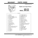
PARTS GUIDE
CODE:00ZAR275//P1E
Digital Laser Copier/Printer
AR-275
MODEL
AR-235
1
Exteriors 1
2
Exteriors 2
3
Delivery tray section
4
OC cover unit(Option AR-VR3)
5
Operation panel unit
6
Frame section
7
Lump unit
8
Optical frame 1
9
Optical frame 2
F
Middle frame
G
550 cassette unit
H
Paper feed section
I
Paper transfer section
J
Side door unit
K
TC unit
L
Multi manual paper feed tray unit
M
Multi manual paper feed unit
N
DV unit
O
Process unit
P
Fusing unit 1
Q
Fusing unit 2
R
Drive unit
S
1st delivery paper unit 1
T
1st delivery paper unit 2
U
2nd delivery paper unit
V
PWB section
W
Rear frame section
X
2nd exteiors
Y
2nd 550 cassette unit
Z
2nd paper feed section
[
2nd paper transfer section
\
2nd drive section
]
Pick up motor unit
^
Job seprator unit(Option AR-TR3)
_
Packing material & accessories
.
MCU PWB
a
IMC PWB
b
LCD backlight PWB
c
KEY/LED R PWB
d
KEY/LED L PWB
e
Option connector PWB
f
2nd Interface PWB
■
Index
SHARP CORPORATION
DEFINITION
The definition of each Rank is as follows and also noted in the list
A : Parts necessary to be stocked as High usage parts.
B : Parts necessary to be stocked as Standard usage parts.
C : Low usage parts.
D : Parts necessary for refurbish.
E : Unit parts recommended to be stocked for efficient after sales service.
B : Parts necessary to be stocked as Standard usage parts.
C : Low usage parts.
D : Parts necessary for refurbish.
E : Unit parts recommended to be stocked for efficient after sales service.
Please note that the lead time for the said parts may be longer than normal parts.
S : Consumable parts.
Please note that the following parts used in Copier under the same description are classified into A or B Rank depending
upon the place used.
upon the place used.
Example : Gear made of Metal, Sprocket, Bearing, Belt made of Rubber, Spring clutch mechanism.
A Rank : The parts which may be with the revolution or loading.
B Rank : Parts similar to A Rank parts, but are not included in Rank A.
A Rank : The parts which may be with the revolution or loading.
B Rank : Parts similar to A Rank parts, but are not included in Rank A.
Because parts marked with "
!
" is indispensable for the machine safety maintenance and operation, it must be replaced with
the parts specific to the product specification.
F
Other than this Parts Guide, please refer to documents Service Manual (including Circuit Diagram) of this model.
F
Please use the 13 digit code described in the right hand corner of front cover of the document, when you place an order.
F
For U.S. only-Use order codes provided in advertising literature. Do not order from parts department.
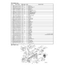
1 Exteriors 1
NO.
PARTS CODE
PRICE
RANK
NEW
MARK
PART
RANK
DESCRIPTION
1
G C A B - 0 0 3 5 Q S Z Z
AK
N
D
Optical left cabinet upper
2
G C A B - 0 0 3 6 Q S Z Z
AH
N
D
Optical left cabinet lower
3
C F I X - 0 0 1 3 Q S 0 1
AK
N
D
Glass fixing plate
4
P S H E Z 0 2 2 0 Q S Z 1
AK
N
C
Shadhing sheet
5
L X - B Z 0 0 2 4 Q S Z Z
AA
N
C
Screw
6
G C A B - 0 0 4 0 Q S Z Z
AX
N
D
Rear cabinet upper
7
C G I D M 0 0 7 7 Q S 0 1
AL
N
C
OR guide
8
L F I X - 0 0 1 1 Q S Z Z
AK
N
D
OC glass fixing plate
9
G C A B - 0 0 3 3 Q S Z Z
AK
N
D
Optical right cabinet upper
10
G C A B - 0 0 3 4 Q S Z Z
AK
N
D
Optical right cabinet lower
11
P G L S P 0 0 0 3 Q S Z Z
BA
B
Table glass
12
G C A B - 0 0 3 1 Q S Z Z
AS
N
D
Optical front cabinet upper
13
G C A B - 0 0 3 2 Q S Z Z
AQ
N
D
Optical front cabinet lower
14
C P N L H 0 0 2 0 Q S 0 1
AK
N
C
Model panel
(AR-235)
C P N L H 0 0 2 0 Q S 0 2
AK
N
C
Model panel
(AR-275)
15
T L A B H 0 3 0 2 Q S Z Z
AG
C
Operation label
1 Exteriors 1
2 Exteriors 2
NO.
PARTS CODE
PRICE
RANK
NEW
MARK
PART
RANK
DESCRIPTION
1
G C A B - 0 0 4 2 Q S Z Z
AP
N
D
Rear cabinet left
2
G C O V - 0 0 2 8 Q S Z Z
BA
N
D
Power supply cover
3
X H B S E 3 0 P 0 8 0 0 0
AA
C
Screw (3
×
8)
4
G C O V - 0 0 2 9 Q S Z Z
AR
N
D
Delivery rear cover upper
5
G C O V - 0 0 3 0 Q S Z Z
AT
N
D
Delivery rear cover lower
6
G C A B - 0 0 4 3 Q S Z Z
AN
N
D
Rear cabinet lower
7
X E B S E 4 0 P 1 0 0 0 0
AA
C
Screw (4
×
10)
8
G C A B - 0 0 4 1 Q S Z Z
BA
N
D
Rear cabinet right
9
G C O V - 0 0 3 4 Q S Z Z
AK
N
D
Rear cabinet memory cover
10
G C O V - 0 0 3 1 Q S Z Z
AK
N
D
Delivery dummy cover
1
2 3
5
5
5
5
5
6
7
8
5
5
5
9
10
12
11
13
14
4
FCP04715
15
– 1 –
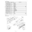
2 Exteriors 2
NO.
PARTS CODE
PRICE
RANK
NEW
MARK
PART
RANK
DESCRIPTION
11
M S P R D 0 1 8 9 Q S Z Z
AB
N
C
Right cabinet spring
12
M L E V P 0 0 6 9 Q S Z Z
AD
N
C
Right cabinet lever
13
G D O R - 0 0 0 3 Q S Z 1
AP
N
D
Right cabinet door
14
N R O L P 1 0 6 0 F C Z Z
AF
C
U-turn roller
15
M S P R T 0 2 2 9 G C A Z
AC
C
FU spring R
16
G C A B - 0 0 3 9 Q S Z Z
AR
N
D
Right cabinet
17
G C O V - 0 0 4 3 Q S Z 1
AS
N
D
OP PWB cover
18
P F I L Z 0 0 1 1 Q S Z Z
AS
N
C
Ozon filter
23
G C A B - 0 0 3 7 Q S Z Z
AL
N
D
Front right cabinet
(U.S.A)
C C A B - 0 0 3 7 Q S 0 1
AN
N
D
Front right cabinet
Except(U.S.A)
24
L S O U - 0 0 3 3 Q S Z Z
AR
N
D
Delivery exetension tray
25
C P N L H 0 0 1 6 Q S 5 1
BD
N
E
Operation panel unit
(U.S.A,U.Kingdom,Australia,New Zealand,Philippines)
C P N L H 0 0 1 6 Q S 5 3
CA
N
E
Operation panel unit
(Canada)
C P N L H 0 0 1 6 Q S 5 5
CB
N
E
Operation panel unit
(Germany,Greece,Cyprus,Turkey,
Poland,Hungary,Czechoslovakia,LAG2,LAG4)
C P N L H 0 0 1 6 Q S 5 6
CB
N
E
Operation panel unit
(Sweden,Finland,Norway,Denmark)
C P N L H 0 0 1 6 Q S 5 4
CA
N
E
Operation panel unit
(Other countries)
26
G C A B - 0 0 3 8 Q S Z Z
AX
N
D
Front cabinet
27
G C O V - 0 0 3 2 Q S Z Z
AE
N
D
Power supply switch cover
(120V)
G C O V - 0 0 3 2 Q S Z 1
AE
N
D
Power supply switch cover
(Other countries)
28
C A R M M 0 0 2 3 Q S 0 1
AD
N
C
Hinge arm R
29
M A R M M 0 0 2 2 Q S Z Z
AC
N
C
Hinge arm L
30
L P I N - 0 2 7 7 F C Z Z
AB
C
Slide pin
31
C C O V - 0 0 2 7 Q S 0 1
AU
N
D
Front cover
(U.S.A)
G C O V - 0 0 2 7 Q S Z Z
AT
N
D
Front cover
(Except U.S.A)
32
D H A I - 0 2 0 5 Q S Z Z
AG
N
C
Oparation unit harness
33
X E B S E 3 0 P 0 8 0 0 0
AA
C
Screw (3
×
8)
34
X E B S E 4 0 P 1 2 0 0 0
AA
C
Screw (4
×
12)
35
X H B S E 4 0 P 1 0 0 0 0
AA
C
Screw (4
×
10)
36
X H B S E 4 0 P 1 8 0 0 0
AB
N
C
Screw (4
×
18)
37
L X - B Z 0 0 2 4 Q S Z Z
AA
N
C
Screw
38
G C O V - 0 0 4 2 Q S Z Z
AK
N
C
Rail dummy cover
40
T L A B Z 0 0 5 8 Q S Z Z
AD
C
Class 1 label
[Except U.S.A,Canada,Taiwan,LAG2,Brazil]
41
T L A B H 0 2 6 4 G C Z Z
AC
C
Service man label
[Europe]
42
T C A U A 0 7 7 0 F C Z Z
AB
C
Service caution card
43
T L A B H 0 3 6 0 Q S Z Z
AD
N
C
Power supply label
(120V)
44
T L A B H 0 3 6 1 Q S Z Z
AD
N
C
Warm heater label
(120V)
45
P S H E Z 0 2 8 1 Q S Z Z
AC
N
C
Damper sheet C
46
P S H E Z 0 2 8 0 Q S Z Z
AE
N
C
Damper sheet B
47
P M L T - 0 0 5 7 Q S Z Z
AC
N
C
Front cabinet cushion
48
P M L T - 0 0 5 9 Q S Z Z
AC
N
C
Front cabinet cushion C
49
P M L T - 0 0 4 6 Q S Z Z
AF
N
C
Front cabinet cushion under
50
P M L T - 0 0 6 2 Q S Z Z
AD
N
C
Delivery rear cover upper cushion B
51
L P L T M 0 2 6 3 Q S Z Z
AP
N
C
Reinforce plate C
52
P M L T - 0 0 4 8 Q S Z Z
AF
N
C
Power supply cover cushion F
53
P M L T - 0 0 4 7 Q S Z Z
AK
N
C
Power supply cover cushion UP
54
P M L T - 0 0 5 0 Q S Z Z
AC
N
C
Power supply cover cushion L corner B
55
P M L T - 0 0 5 1 Q S Z Z
AF
N
C
Power supply cover left cushion A
56
P M L T - 0 0 5 2 Q S Z Z
AD
N
C
Power supply cover left cushion B
57
P M L T - 0 0 6 5 Q S Z Z
AD
N
C
Rail dummy cover cushion
2 Exteriors 2
53
54
43
44
1
3
2
3
7
17
37
7
7
7
9
3
4
5
3
33
12
11
15
14
13
16
7
10
23
24
37
25
32
33
33
27
26
34
30
29
36
31
35
28
3
7
3
15
14
35
8
6
FCP04716
38
37
40
41
42
18
46
45
45
57
52
50
56
55
54
54
50
49
51
47
48
– 2 –
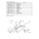
3 Delivery tray section
NO.
PARTS CODE
PRICE
RANK
NEW
MARK
PART
RANK
DESCRIPTION
1
X E P S D 3 0 P 1 4 X 0 0
AA
C
Screw (3
×
14)
2
P C O V P 0 0 8 5 Q S Z Z
AP
N
C
Exhaust cover
3
P B O X - 0 0 1 3 Q S Z Z
AK
N
C
Exhaust fan box
4
X E B S D 3 0 P 1 0 0 0 0
AA
C
Screw (3
×
10)
5
N F A N P 0 0 0 6 Q S Z Z
AT
N
B
Exhaust fan motor
6
P D U C - 0 0 0 4 Q S Z Z
AL
N
C
Exhaust fan duct
8
P B O X - 0 0 0 6 Q S Z Z
AF
N
D
Delivery sensor BOX
9
V H P G P 1 S 7 3 P + - 1
AF
N
B
Photo sensor (GP1S73P)
10
M L E V P 0 0 6 8 Q S Z Z
AC
N
C
Delivery tray actuator
11
D H A I - 0 2 4 4 Q S Z Z
AD
N
C
Delivery paper detect sensor harness
12
X E B S D 3 0 P 3 0 0 0 0
AA
C
Screw (3
×
30)
13
P M L T - 0 0 4 3 Q S Z Z
AE
N
C
Delivery cushion
14
L S O U - 0 0 2 3 Q S Z Z
BA
N
D
Delivery tray
15
L H L D W 1 0 9 8 H C Z Z
AB
C
Holder
16
P S H E Z 0 2 9 2 Q S Z Z
AD
N
C
Delivery tray mylar
17
P S H E Z 0 2 8 6 Q S Z Z
AE
N
C
Exhaust fan mylar
18
P S H E Z 0 2 9 6 Q S Z Z
AA
N
C
Ozone duct dumper sheet
19
P S H E Z 0 2 8 2 Q S Z Z
AC
N
C
Dumper sheet D
20
P S H E Z 0 2 8 3 Q S Z Z
AB
N
C
Fan motor sheet
21
P M L T - 0 0 5 6 Q S Z Z
AD
N
C
Delivery tray back cushion
22
P M L T - 0 0 5 5 Q S Z Z
AH
N
C
Delivery tray back cushion A
3 Delivery tray section
FCP04717
1
4
12
5
3
6
8
9
10
11
2
15
4
13
14
16
17
19
20
20
18
18
18
18
21
21
22
4
– 3 –

