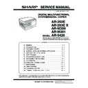
Sharp AR-203 (serv.man5) Service Manual ▷ View online
CONTENTS
[1]
GENERAL
1. Major functions . . . . . . . . . . . . . . . . . . . . . . . . . . . . . . . 1-1
[2]
SPECIFICATIONS
1. Basic Specifications . . . . . . . . . . . . . . . . . . . . . . . . . . . 2-1
2. Operation specifications . . . . . . . . . . . . . . . . . . . . . . . . 2-1
3. Copy performance . . . . . . . . . . . . . . . . . . . . . . . . . . . . 2-2
4. GDI printer (AR-203E only). . . . . . . . . . . . . . . . . . . . . . 2-3
5. SPLC printer (AR-M200/M201). . . . . . . . . . . . . . . . . . . 2-3
6. Scan function (AR-203E/M200/M201) . . . . . . . . . . . . . 2-3
[3]
CONSUMABLE PARTS
1. Supply system table . . . . . . . . . . . . . . . . . . . . . . . . . . . 3-1
A. Europe Subsidiary (AR-203E/5420/M200/M201),
SCA/SCNZ (AR-203E/M201) . . . . . . . . . . . . . . . . . . 3-1
B. Asia Subsidiary (AR-203E/M201). . . . . . . . . . . . . . . 3-1
C. SMEF/Distributor (AR-203E/M201) . . . . . . . . . . . . . 3-1
D. SRH (AR-203E/M201) . . . . . . . . . . . . . . . . . . . . . . . 3-1
2. Environmental . . . . . . . . . . . . . . . . . . . . . . . . . . . . . . . . 3-2
3. Production control number (lot No.) identification . . . . . 3-2
4. Toner cartridge replacement. . . . . . . . . . . . . . . . . . . . . 3-3
[4]
EXTERNAL VIEWS AND INTERNAL STRUCTURES
1. Appearance . . . . . . . . . . . . . . . . . . . . . . . . . . . . . . . . . 4-1
2. Internal . . . . . . . . . . . . . . . . . . . . . . . . . . . . . . . . . . . . . 4-1
3. Operation panel . . . . . . . . . . . . . . . . . . . . . . . . . . . . . . 4-2
A. AR-203E/5420 . . . . . . . . . . . . . . . . . . . . . . . . . . . . . 4-2
B. AR-M200/M201 . . . . . . . . . . . . . . . . . . . . . . . . . . . . 4-3
4. Motors and solenoids . . . . . . . . . . . . . . . . . . . . . . . . . . 4-5
5. Sensors and switches . . . . . . . . . . . . . . . . . . . . . . . . . . 4-6
6. PWB unit . . . . . . . . . . . . . . . . . . . . . . . . . . . . . . . . . . . . 4-7
7. Cross sectional view . . . . . . . . . . . . . . . . . . . . . . . . . . . 4-8
[5]
UNPACKING AND INSTALLATION
1. Copier installation . . . . . . . . . . . . . . . . . . . . . . . . . . . . . 5-1
2. Cautions on handling . . . . . . . . . . . . . . . . . . . . . . . . . . 5-1
3. Checking packed components and accessories. . . . . . 5-1
4. Unpacking . . . . . . . . . . . . . . . . . . . . . . . . . . . . . . . . . . . 5-2
5. Removing protective packing materials . . . . . . . . . . . . 5-2
6. Developer unit installation. . . . . . . . . . . . . . . . . . . . . . . 5-2
7. Toner cartridge installation . . . . . . . . . . . . . . . . . . . . . . 5-3
8. Loading paper . . . . . . . . . . . . . . . . . . . . . . . . . . . . . . . . 5-4
9. Power to copier . . . . . . . . . . . . . . . . . . . . . . . . . . . . . . . 5-4
10. Software (AR-203E/M200/M201) . . . . . . . . . . . . . . . . . 5-4
A. Before installation . . . . . . . . . . . . . . . . . . . . . . . . . . . 5-4
B. Installing the software. . . . . . . . . . . . . . . . . . . . . . . . 5-5
C. Setting up Button Manager. . . . . . . . . . . . . . . . . . . . 5-7
11. Interface . . . . . . . . . . . . . . . . . . . . . . . . . . . . . . . . . . . . 5-9
A. USB . . . . . . . . . . . . . . . . . . . . . . . . . . . . . . . . . . . . . 5-9
12. Moving . . . . . . . . . . . . . . . . . . . . . . . . . . . . . . . . . . . . . 5-9
13. Scanner moisture-proof kit . . . . . . . . . . . . . . . . . . . . . . 5-9
A. Components . . . . . . . . . . . . . . . . . . . . . . . . . . . . . . . 5-9
B. Precautions at installation . . . . . . . . . . . . . . . . . . . . 5-9
C. Attachment method . . . . . . . . . . . . . . . . . . . . . . . . . 5-9
[6]
COPY PROCESS
1. Functional diagram . . . . . . . . . . . . . . . . . . . . . . . . . . . . 6-1
2. Outline of print process . . . . . . . . . . . . . . . . . . . . . . . . . 6-2
3. Actual print process . . . . . . . . . . . . . . . . . . . . . . . . . . . 6-2
[7]
OPERATIONAL DESCRIPTIONS
1.
Outline of operation. . . . . . . . . . . . . . . . . . . . . . . . . . . . 7-1
2.
Scanner section . . . . . . . . . . . . . . . . . . . . . . . . . . . . . . 7-2
A. Scanner unit . . . . . . . . . . . . . . . . . . . . . . . . . . . . . . . 7-2
B. Optical system . . . . . . . . . . . . . . . . . . . . . . . . . . . . . 7-2
C. Drive system. . . . . . . . . . . . . . . . . . . . . . . . . . . . . . . 7-2
3.
Laser unit . . . . . . . . . . . . . . . . . . . . . . . . . . . . . . . . . . . 7-3
A. Basic structure . . . . . . . . . . . . . . . . . . . . . . . . . . . . . 7-3
B. Laser beam path. . . . . . . . . . . . . . . . . . . . . . . . . . . . 7-3
C. Composition . . . . . . . . . . . . . . . . . . . . . . . . . . . . . . . 7-3
4.
Fuser section . . . . . . . . . . . . . . . . . . . . . . . . . . . . . . . . 7-3
A. General description . . . . . . . . . . . . . . . . . . . . . . . . . 7-4
5.
Paper feed section and paper transport section . . . . . . 7-4
A. Paper transport path and general operations . . . . . . 7-4
6.
D-D (Duplex to Duplex) mode paper/
document transport (Duplex model)
(AR-M201 only) . . . . . . . . . . . . . . . . . . . . . . . . . . . . . . . 7-7
document transport (Duplex model)
(AR-M201 only) . . . . . . . . . . . . . . . . . . . . . . . . . . . . . . . 7-7
A. Initial state . . . . . . . . . . . . . . . . . . . . . . . . . . . . . . . . 7-7
B. Front copy. . . . . . . . . . . . . . . . . . . . . . . . . . . . . . . . . 7-7
C. Back copy . . . . . . . . . . . . . . . . . . . . . . . . . . . . . . . . . 7-7
7.
Shifter (AR-M200/M201) . . . . . . . . . . . . . . . . . . . . . . . . 7-8
[8]
DISASSEMBLY AND ASSEMBLY
1.
High voltage section . . . . . . . . . . . . . . . . . . . . . . . . . . . 8-1
A. List . . . . . . . . . . . . . . . . . . . . . . . . . . . . . . . . . . . . . . 8-1
B. Drum replacement . . . . . . . . . . . . . . . . . . . . . . . . . . 8-1
C. Disassembly procedure . . . . . . . . . . . . . . . . . . . . . . 8-3
D. Assembly procedure . . . . . . . . . . . . . . . . . . . . . . . . . 8-3
E. Charger wire cleaning. . . . . . . . . . . . . . . . . . . . . . . . 8-4
F. Charger wire replacement . . . . . . . . . . . . . . . . . . . . 8-4
2.
Operation panel section . . . . . . . . . . . . . . . . . . . . . . . . 8-4
A. List . . . . . . . . . . . . . . . . . . . . . . . . . . . . . . . . . . . . . . 8-4
B. Disassembly procedure . . . . . . . . . . . . . . . . . . . . . . 8-4
C. Assembly procedure . . . . . . . . . . . . . . . . . . . . . . . . . 8-5
3.
Optical section . . . . . . . . . . . . . . . . . . . . . . . . . . . . . . . 8-5
A. List . . . . . . . . . . . . . . . . . . . . . . . . . . . . . . . . . . . . . . 8-5
B. Disassembly procedure . . . . . . . . . . . . . . . . . . . . . . 8-5
C. Assembly procedure . . . . . . . . . . . . . . . . . . . . . . . . . 8-7
4.
Fusing section . . . . . . . . . . . . . . . . . . . . . . . . . . . . . . . . 8-7
A. List . . . . . . . . . . . . . . . . . . . . . . . . . . . . . . . . . . . . . . 8-7
B. Disassembly procedure . . . . . . . . . . . . . . . . . . . . . . 8-7
C. Assembly procedure . . . . . . . . . . . . . . . . . . . . . . . . 8-10
5.
Tray paper feed/transport section . . . . . . . . . . . . . . . . 8-10
A. List . . . . . . . . . . . . . . . . . . . . . . . . . . . . . . . . . . . . . 8-10
B. Disassembly procedure . . . . . . . . . . . . . . . . . . . . . 8-10
C. Assembly procedure . . . . . . . . . . . . . . . . . . . . . . . . 8-16
6.
Manual paper feed section . . . . . . . . . . . . . . . . . . . . . 8-17
A. List . . . . . . . . . . . . . . . . . . . . . . . . . . . . . . . . . . . . . 8-17
B. Disassembly procedure . . . . . . . . . . . . . . . . . . . . . 8-17
C. Assembly procedure . . . . . . . . . . . . . . . . . . . . . . . . 8-18
D. Pressure plate holder attachment. . . . . . . . . . . . . . 8-19
7.
Rear frame section . . . . . . . . . . . . . . . . . . . . . . . . . . . 8-19
A. List . . . . . . . . . . . . . . . . . . . . . . . . . . . . . . . . . . . . . 8-19
B. Disassembly procedure . . . . . . . . . . . . . . . . . . . . . 8-19
C. Assembly procedure . . . . . . . . . . . . . . . . . . . . . . . . 8-20
8
Power section . . . . . . . . . . . . . . . . . . . . . . . . . . . . . . . 8-20
A. List . . . . . . . . . . . . . . . . . . . . . . . . . . . . . . . . . . . . . 8-20
B. Disassembly procedure . . . . . . . . . . . . . . . . . . . . . 8-20
C. Assembly procedure. . . . . . . . . . . . . . . . . . . . . . . . 8-20
9. DV unit section . . . . . . . . . . . . . . . . . . . . . . . . . . . . . . 8-20
A. Developer . . . . . . . . . . . . . . . . . . . . . . . . . . . . . . . . 8-20
B. DV seal. . . . . . . . . . . . . . . . . . . . . . . . . . . . . . . . . . 8-21
C. DV blade. . . . . . . . . . . . . . . . . . . . . . . . . . . . . . . . . 8-21
D. DV doctor . . . . . . . . . . . . . . . . . . . . . . . . . . . . . . . . 8-21
E. DV sensor. . . . . . . . . . . . . . . . . . . . . . . . . . . . . . . . 8-22
10. Duplex motor section (AR-M201 only) . . . . . . . . . . . . 8-22
A. List . . . . . . . . . . . . . . . . . . . . . . . . . . . . . . . . . . . . . 8-22
B. Disassembly procedure . . . . . . . . . . . . . . . . . . . . . 8-22
C. Assembly procedure. . . . . . . . . . . . . . . . . . . . . . . . 8-22
11. Reverse roller section (AR-M201 only). . . . . . . . . . . . 8-22
A. List . . . . . . . . . . . . . . . . . . . . . . . . . . . . . . . . . . . . . 8-22
B. Disassembly procedure . . . . . . . . . . . . . . . . . . . . . 8-22
C. Assembly procedure. . . . . . . . . . . . . . . . . . . . . . . . 8-22
[9]
ADJUSTMENTS
1. Optical section . . . . . . . . . . . . . . . . . . . . . . . . . . . . . . . 9-1
A. Copy magnification ratio adjustment . . . . . . . . . . . . 9-1
B. Image position adjustment . . . . . . . . . . . . . . . . . . . . 9-2
2. Copy density adjustment . . . . . . . . . . . . . . . . . . . . . . . 9-4
A. Copy density adjustment timing . . . . . . . . . . . . . . . . 9-4
B. Note for copy density adjustment . . . . . . . . . . . . . . . 9-4
C. Necessary tool for copy density adjustment . . . . . . . 9-4
D. Features of copy density adjustment . . . . . . . . . . . . 9-4
E. Copy density adjustment procedure. . . . . . . . . . . . . 9-5
3. High voltage adjustment . . . . . . . . . . . . . . . . . . . . . . . . 9-5
A. Main charger (Grid bias). . . . . . . . . . . . . . . . . . . . . . 9-5
B. DV bias check . . . . . . . . . . . . . . . . . . . . . . . . . . . . . 9-6
4. Duplex adjustment . . . . . . . . . . . . . . . . . . . . . . . . . . . . 9-6
A. Adjusting the paper reverse position in memory
for duplex copying (AR-M200/M201) . . . . . . . . . . . . 9-6
B. Adjusting trailing edge void in duplex copy mode
(AR-M201) . . . . . . . . . . . . . . . . . . . . . . . . . . . . . . . . 9-6
5. Automatic black level correction . . . . . . . . . . . . . . . . . . 9-7
[10] SIMULATION, TROUBLE CODES
1. Entering the simulation mode . . . . . . . . . . . . . . . . . . . 10-1
2. Key rule. . . . . . . . . . . . . . . . . . . . . . . . . . . . . . . . . . . . 10-1
3. List of simulations . . . . . . . . . . . . . . . . . . . . . . . . . . . . 10-1
4. Descriptions of various simulations. . . . . . . . . . . . . . . 10-3
5. Trouble codes . . . . . . . . . . . . . . . . . . . . . . . . . . . . . . 10-40
A. Trouble codes list . . . . . . . . . . . . . . . . . . . . . . . . . 10-40
B. Details of trouble codes . . . . . . . . . . . . . . . . . . . . 10-41
[11] MAINTENANCE
1. Maintenance table . . . . . . . . . . . . . . . . . . . . . . . . . . . 11-1
2. Maintenance display system. . . . . . . . . . . . . . . . . . . . 11-1
3. Remaining toner indication . . . . . . . . . . . . . . . . . . . . . 11-1
[12] USER PROGRAM
1. Functions that can be set with user programs . . . . . . 12-1
2. Toner save mode (AR-203E/5420) . . . . . . . . . . . . . . . 12-1
3. User programs (AR-203E/5420) . . . . . . . . . . . . . . . . . 12-1
4. User programs (AR-M200/M201) . . . . . . . . . . . . . . . . 12-2
A. Copy mode . . . . . . . . . . . . . . . . . . . . . . . . . . . . . . . 12-3
B. Print mode . . . . . . . . . . . . . . . . . . . . . . . . . . . . . . . 12-4
[13] ELECTRICAL SECTION
1.
Block diagram . . . . . . . . . . . . . . . . . . . . . . . . . . . . . . . 13-1
A. Overall block diagram (AR-203E/5420) . . . . . . . . . 13-1
B. Overall block diagram (AR-M200/M201) . . . . . . . . 13-2
2.
Actual wiring diagram . . . . . . . . . . . . . . . . . . . . . . . . . 13-3
A. MCU PWB (AR-203E/5420) . . . . . . . . . . . . . . . . . . 13-3
B. MCU PWB (AR-M200/M201) . . . . . . . . . . . . . . . . . 13-4
C. SPF unit (AR-203E optional only). . . . . . . . . . . . . . 13-5
D. RSPF unit (AR-M200/M201 optional only) . . . . . . . 13-5
E. 2nd cassette unit
(AR-203E/M200/M201 optional only) . . . . . . . . . . . 13-5
F. Network box and FAX
(AR-M200/M201 optional only). . . . . . . . . . . . . . . . 13-6
3.
Signal name list. . . . . . . . . . . . . . . . . . . . . . . . . . . . . . 13-6
4.
Circuit diagram . . . . . . . . . . . . . . . . . . . . . . . . . . . . . . 13-9
A. MCU PWB (AR-203E/5420) . . . . . . . . . . . . . . . . . . 13-9
B. MCU PWB (AR-M200/M201) . . . . . . . . . . . . . . . . 13-21
C. OPE PWB (AR-203E/5420) . . . . . . . . . . . . . . . . . 13-37
D. OPERATION PWB (AR-M200/M201). . . . . . . . . . 13-38
[14] FIRMWARE DOWNLOAD PROCEDURES
1.
Initial setting (Serial number setting procedures) . . . . 14-1
2.
Download procedures . . . . . . . . . . . . . . . . . . . . . . . . . 14-1
3.
Version acquisition procedures . . . . . . . . . . . . . . . . . . 14-3
4.
EEPROM data acquisition procedure . . . . . . . . . . . . . 14-4
5.
Installing procedures . . . . . . . . . . . . . . . . . . . . . . . . . . 14-5
AR-203E/5420/M200/M201 GENERAL 1 - 1
[1] GENERAL
1. Major functions
Configurations
Descriptions of items
CPM:
Copy speed (Copies Per Minute)
PPM:
Print speed (Print Per Minute)
SB/MB:
SB = Manual feed single bypass,
MB = Manual feed multi-bypass
MB = Manual feed multi-bypass
2 Tray:
Second cassette unit (AR-D33)
SPF:
Original feed unit (AR-SP9)
R-SPF:
Duplex original feed unit (AR-RP9)
Color Scanner:
Color scanner function
GDI printer:
GDI printer function with USB.
SPLC printer:
SPLC printer function with USB.
E-SORT:
Electronic sort function
Duplex:
Auto duplex copy/print function
Shifter:
Job separator function
USB:
Interface port (USB)
RJ45:
Interface port (Network)
FAX: FAX
function
(AR-FX13)
External NIC:
AR-NB2A
Descriptions of table
: Standard
provision
: No function or no option available
Opt: Option
Item
Model
CPM
(A4)
PPM
(A4)
SB/
MB
2 Tray
SPF
R-SPF
Color
Scanner
GDI
printer
SPLC
printer
E-
SORT
Duplex Shifter
USB
RJ45
FAX
External
NIC
AR-203E 20CPM 15PPM
MB
Opt
Opt
✕
✕
✕
✕
✕
(2.0 full)
✕
✕
✕
AR-5420 20CPM
—
MB
✕
✕
✕
✕
✕
✕
✕
✕
✕
✕
✕
✕
✕
AR-M200 20CPM 20PPM
MB
Opt
✕
Opt
✕
✕
(2.0 Hi)
✕
Opt
Opt
AR-M201 20CPM 20PPM
MB
Opt
✕
Opt
✕
(2.0 Hi)
✕
Opt
Opt
AR-SP9
(Options)
AR-D33
AR-203E/AR-5420
AR-M200/AR-M201
AR-M200/AR-M201
AR-NB2A
AR-FX13
AR-RP9
AR-203E/5420/M200/M201 SPECIFICATIONS 2 - 1
[2] SPECIFICATIONS
1. Basic Specifications
2. Operation specifications
Item
Type
Desktop
Copy system
Dry, electrostatic
Segment (class)
Digital personal copier
Copier dimensions
AR-203E/5420: 518mm (W) x 445mm (D) x 298mm (H) (20-1/2" (W) x 17-5/8" (D) x 11-3/4" (H))
AR-M200/M201: 518mm (W) x 452mm (D) x 298mm (H) (20-1/2" (W) x 17-7/8" (D) x 11-3/4" (H))
AR-M200/M201: 518mm (W) x 452mm (D) x 298mm (H) (20-1/2" (W) x 17-7/8" (D) x 11-3/4" (H))
Weight (Approximately)
AR-203E/5420: 16.6kg (36.5 lbs.)
AR-M200: 19.8kg (43.7 lbs.)
AR-M201: 20.5kg (45.2 lbs.)
AR-M200: 19.8kg (43.7 lbs.)
AR-M201: 20.5kg (45.2 lbs.)
Toner cartridge not included
Section, item
Details
Paper feed
section
section
Paper feed system
1 tray (250 sheets) + multi-bypass (50 sheets)
AB system
Tray paper feed section
Paper size
A4, B5, A5 (Landscape)
Paper weight
56 - 80g/m
2
Paper feed capacity
250 sheets
Kinds
Standard paper, specified paper, recycled paper
Remark
User adjustment of paper guide available
Multi-bypass paper
feed section
feed section
Paper size
A4, B5, A5, B6, A6 (Landscape)
Paper weight
56 - 128g/m
2
Paper feed capacity
50 sheets
Kinds
Standard paper, specified paper, recycled paper, OHP,
Label, Envelop (Single copy)
Label, Envelop (Single copy)
Remark
User adjustment of paper guide available
Inch
system
system
Tray paper feed section
Paper size
8-1/2" x 14", 8-1/2" x 11", 8-1/2" x 5-1/2" (Landscape)
Paper weight
15 - 21 lbs.
Paper feed capacity
250 sheets
Kinds
Standard paper, specified paper, recycled paper
Remark
User adjustment of paper guide available
Multi-bypass paper
feed section
feed section
Paper size
8-1/2" x 14", 8-1/2" x 11", 8-1/2" x 5-1/2", 3-1/2" x 5-1/2"
(Landscape)
(Landscape)
Paper weight
15 - 34.5 lbs.
Paper feed capacity
50 sheets
Kinds
Standard paper, specified paper, recycled paper, OHP,
Label, Envelop (Single copy)
Label, Envelop (Single copy)
Remark
User adjustment of paper guide available
Paper exit section
Exit way
Face down
Capacity of output tray
200 sheets
Originals
Original set
Center Registration (left edge)
Max. original size
A4 (8-1/2" x 14")
Original kinds
sheet, book
Original size detection
None
Optical
section
section
Scanning
section
section
Scanning system
3 CCDs (RGB) sensor scanning by lighting white lamp
CCD sensor
Resolution
600 dpi
Lighting lamp
Type
CCFL
Voltage
560Vrms
Power consumption
2.8W
Output data
Output: R, G, B 1 or 8 bits/pixel / Input: A/D 16 bits (12 bits
actual)
actual)
Writing
section
section
Writing system
Writing to OPC drum by the semiconductor laser
Laser unit
Resolution
600 dpi
Image forming
Photoconductor
Type
OPC (30ø)
Life
25K
Charger
Charging system
Saw-tooth charging with a grid, / (-) scorotron discharge
Transfer system
(+) DC corotron system
Separation system
(-) DC corotron system
Developing
Developing system
Dry, 2-component magnetic brush development system
Cleaning
Cleaning system
Counter blade system (Counter to rotation)

