Sharp AM-400 (serv.man5) Service Manual ▷ View online
AM-400DE
5 – 25
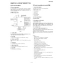
[7] Data flow chart
1. COPY
2. FAX/SEND
3. FAX RECEIVE
4. PC PRINT
5. PC SCAN
CIS
SDRAM
(IC4)
Laser Scan
Unit
1
2
4
Control PWB
3
OA-2000
(IC1)
5
LSU I/F controlled
by Printer CPU
Printing
CIS
SDRAM
(IC4)
LIU PWB
1
2
4
Control PWB
3
OA-2000
(IC1)
5
FAX MODEM
(IC18)
PSTN
TEL LINE
TEL LINE
LIU PWB
FAX
MODEM
(IC18)
OA-2000
(IC1)
1
SDRAM
(IC4)
PSTN
LSU I/F
controlled by
Printer CPU
Control PWB
2
3
4
6
Laser Scan
Unit
Printing
PC
SDRAM
(IC4)
Laser Scan
Unit
1
2
4
Control PWB
3
OA-2000
(IC1)
5
LSU I/F
controlled by
Printer CPU
Printing
USB
CIS
SDRAM
(IC4)
1
2
4
Control PWB
3
OA-2000
(IC1)
PC
USB
AM-400DE
5 – 26
[8] Troubleshooting
1. Printer error code
2. Scanner message
PAPER JAM
The roller sensor could not detect its home position
after driving the pick up motor for the specified period.
SYSTEM ERROR [P2]
The printer controller detected the optical unit (LSU)
error.
SYSTEM ERROR [P3]
Thermistor error was detected.
SYSTEM ERROR [P4]
ROM or RAM error was detected on the printer
control unit.
SYSTEM ERROR [P5]
High temperature error was detected.
SYSTEM ERROR [P6]
Low temperature error was detected.
SYSTEM ERROR [P7]
Communication error between the main controller
and the printer controller was detected.
The roller sensor could not become NOT-Active after
passing the specified period from picking up paper.
The external interrupt signal for optical unit (LSU) or
High-voltage control did not become active after
passing the specified period.
CHK SCANNER LOCK
The scanner unit could not detect change point of
home postion. (ON -> OFF or OFF -> ON)
AM-400DE
5 – 27
3. Troubleshooting of control PWB
Display Error
on LCD
Pickup Motor Error
Not rotate
or shortage torque
Not detect roller sensor
PAPER JAM
R265~R268
IC32 (driver)
F6 (fuse)
IC21 (Printer CPU)
CNROLSNS
(Connector)
C,R on route
of CNROLSNS~IC21
D15 (zener diode)
R331~R334
IC21 (Printer CPU)
1
A
LSU Error
SYSTEM ERROR
[P2]
H/V-unit control-circuit
Error
Optical Error
(Laser)
+5V-Regulator Circuit
fail
Control signal fail
CNPM
(Connector)
Q14(Transistor)
Q15(Transistor)
R301
IC21 (Printer CPU)
F5 (fuse)
C202,C206,C207
D14 (Diode)
IC22
(Regulator IC)
R277
Scanning-motor Error
CNLSR
(Connector)
R,C around above
ICs
IC22
(Regulator IC)
IC25~ IC27
IC22
(Regulator IC)
IC23,IC25,
IC28,IC29
R,C around above
ICs
A
2
B
AM-400DE
5 – 28
Thermister Error
SYSTEM ERROR
[P3]
SYSTEM ERROR
[P4]
Printer Control Microcomputer
ROM/RAM Error
Fuser Temp.
too High
SYSTEM ERROR
[P5]
Temp. detect
Error
Heater control Error
/HLON, /PWRLY signal
IC21 (Printer CPU)
IC22
(Regulator IC)
D13 (Diode)
C, R on route
of CNRTH~IC21
CNRTH (Connector)
IC21 (Printer CPU)
CNRTH (Connector)
Other parts on route
of CNRTH~ IC21
IC21 (Printer CPU)
CNPW-12pin/13pin
IC32 (driver)
B
3
4
5
C
Fuser Temp.
too Low
SYSTEM ERROR
[P6]
Temp. detect
Error
Heater control
Error
/HLON, /PWRLY
signal
Safety circuit
No detect zerocross
signal (/ZC)
IC21 (Printer CPU)
CNRTH (Connector)
C, R on route
of CNRTH~IC21
IC21 (Printer CPU)
CNPW-12pin/13pin
IC32 (driver)
R335, R336
IC31 (Comparator)
IC25,IC29,IC33
R, C around above
ICs
R, C around above
IC31
IC21 (Printer CPU)
C, R on route
of CNPW-14~IC21
CNPW-14pin
C
D
6
Click on the first or last page to see other AM-400 (serv.man5) service manuals if exist.

