Sharp AL-1566 (serv.man13) Service Manual ▷ View online
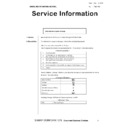
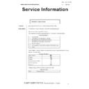
AL-1556/1566 TEST COMMAND, FAX SOFT SWITCH, TROUBLE CODES 10 - 69
E7
11
Content Shading trouble (White correction)
Detail
Detail
The CCD white scan level is abnormal when the
shading.
shading.
Cause
Improper connection of the CCD unit flat cable
Dirt on the mirror, the lens, and the reference
white plate
Copy lamp lighting abnormality
CCD unit abnormality
MCU PWB abnormality
(When occurred in the SPF scan position.)
Improper installation of the mirror unit
Dirt on the mirror, the lens, and the reference
white plate
Copy lamp lighting abnormality
CCD unit abnormality
MCU PWB abnormality
(When occurred in the SPF scan position.)
Improper installation of the mirror unit
Check
and
remedy
and
remedy
Clean the mirror, lens, and the reference white
plate.
Check the light quantity and lighting status of
the copy lamp (TC 05-03).
Check the MCU PWB.
plate.
Check the light quantity and lighting status of
the copy lamp (TC 05-03).
Check the MCU PWB.
16
Content Abnormal laser output
Detail
Detail
When the laser output is stopped, HSYNC is
detected.
detected.
Cause
Laser abnormality
MCU PWB abnormality.
MCU PWB abnormality.
Check
and
remedy
and
remedy
Check the laser emitting diode operation.
Replace the MCU PWB.
Replace the MCU PWB.
F5
02
Content Copy lamp lighting abnormality
Detail
Detail
The copy lamp does not turn on.
Cause
Copy lamp abnormality
Copy lamp harness abnormality
CCD PWB harness abnormality.
Copy lamp harness abnormality
CCD PWB harness abnormality.
Check
and
remedy
and
remedy
Use TC 5-3 to check the copy lamp operations.
When the copy lamp lights up.
Check the harness and the connector between
the CCD unit and the MCU PWB.
When the copy lamp does not light up.
Check the harness and the connector between
the copy lamp unit and the MCU PWB.
Replace the copy lamp unit.
Replace the MCU PWB.
When the copy lamp lights up.
Check the harness and the connector between
the CCD unit and the MCU PWB.
When the copy lamp does not light up.
Check the harness and the connector between
the copy lamp unit and the MCU PWB.
Replace the copy lamp unit.
Replace the MCU PWB.
F6
10
Content FAX board trouble (AL-1566)
Detail
Detail
Communication trouble between MCU and FAX
control PWB
control PWB
Cause
FAX control PWB connector disconnection
Defective harness between FAX control PWB
and MCU PWB
Motherboard connector pin breakage
FAX control PWB ROM error/Data error
IC on FAX PWB causes abnormality
Defective harness between FAX control PWB
and MCU PWB
Motherboard connector pin breakage
FAX control PWB ROM error/Data error
IC on FAX PWB causes abnormality
Check
and
remedy
and
remedy
Check connector/harness of FAX control PWB
and MCU PWB.
Check the grounding of the copier.
Check FAX control PWB ROM.
Replace the FAX PWB.
and MCU PWB.
Check the grounding of the copier.
Check FAX control PWB ROM.
Replace the FAX PWB.
H2
00
Content Thermistor open
Detail
Detail
The thermistor is open.
The fusing unit is not installed.
The fusing unit is not installed.
Cause
Thermistor abnormality
Control PWB abnormality
Fusing section connector disconnection
The fusing unit is not installed.
Control PWB abnormality
Fusing section connector disconnection
The fusing unit is not installed.
Check
and
remedy
and
remedy
Check the harness and the connector between
the thermistor and the PWB.
Use TC 14 to clear the self diagnostic display.
the thermistor and the PWB.
Use TC 14 to clear the self diagnostic display.
Main
code
code
Sub
code
Details of trouble
H3
00
Content Heat roller high temperature detection
Detail
Detail
The fusing temperature exceeds 240°C.
Cause
Thermistor abnormality
Control PWB abnormality
Fusing section connector disconnection.
Control PWB abnormality
Fusing section connector disconnection.
Check
and
remedy
and
remedy
Use TC 5-02 to check the heater lamp blinking
operation.
When the lamp blinks normally.
Check the thermistor and its harness.
Check the thermistor input circuit on the control
PWB.
When the lamp keeps ON.
Check the power PWB and the lamp control
circuit on the MCU PWB.
Use TC 14 to clear the self diagnostic display.
operation.
When the lamp blinks normally.
Check the thermistor and its harness.
Check the thermistor input circuit on the control
PWB.
When the lamp keeps ON.
Check the power PWB and the lamp control
circuit on the MCU PWB.
Use TC 14 to clear the self diagnostic display.
H4
00
Content Heat roller low temperature detection
Detail
The fusing temperature does not reach 185°C
within 27 sec of turning on the power, or the
fusing temperature keeps at 140°C.
within 27 sec of turning on the power, or the
fusing temperature keeps at 140°C.
Cause
Thermistor abnormality
Heater lamp abnormality
Thermostat abnormality
Control PWB abnormality
Heater lamp abnormality
Thermostat abnormality
Control PWB abnormality
Check
and
remedy
and
remedy
Use TC 5-02 to check the heater lamp blinking
operation.
When the lamp blinks normally.
Check the thermistor and its harness.
Check the thermistor input circuit on the control
PWB.
When the lamp does not light up.
Check for disconnection of the heater lamp and
the thermostat. Check the interlock switch.
Check the power PWB and the lamp control
circuit on the MCU PWB.
Use TC 14 to clear the self diagnostic display.
L1
00
Content Feeding is not completed within the specified
time after starting feeding. (The scan head
locking switch is locked)
locking switch is locked)
Detail
The white area and the black marking on the
shading plate are used to obtain the difference
in the CCD level values for judgment of lock.
When the difference in the levels of which and
black is small, it is judged that the black mark
could not be scanned by lock and the trouble
code “L1” is displayed.
shading plate are used to obtain the difference
in the CCD level values for judgment of lock.
When the difference in the levels of which and
black is small, it is judged that the black mark
could not be scanned by lock and the trouble
code “L1” is displayed.
Cause
The scan head is locked by the lock switch.
Mirror unit abnormality
The scanner wire is disconnected.
The origin detection sensor abnormality
Mirror motor harness abnormality
Mirror unit abnormality
The scanner wire is disconnected.
The origin detection sensor abnormality
Mirror motor harness abnormality
Check
and
remedy
and
remedy
Check to confirm that the scan head lock switch
is released.
Use TC 1-1 to check the mirror reciprocating
operations.
When the mirror does not feed.
Check for disconnection of the scanner wire.
Check the harness and the connector between
the mirror motor and the MCU PWB.
Replace the mirror unit.
Replace the MCU PWB.
When the mirror does feed.
Use TC 1-2 to check the mirror home position
sensor.
Main
code
code
Sub
code
Details of trouble
AL-1556/1566 TEST COMMAND, FAX SOFT SWITCH, TROUBLE CODES 10 - 70
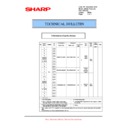
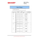
7. Communication error codes (AL-1566)
A. Error code identification
Communication error xx (xxxx)
(In print out, the communication error display is made. In FAX status
check, “NGxxxxxx” is displayed.
check, “NGxxxxxx” is displayed.
When transmission or reception is not executed normally due to distur-
bance in protocol signals and image signals by the trouble in the line,
the code of 6 digits is displayed on the transmission result check menu
(reception result check menu).
bance in protocol signals and image signals by the trouble in the line,
the code of 6 digits is displayed on the transmission result check menu
(reception result check menu).
Upper 2 digits of a communication error code: 00 – 58 (error code) is
displayed. (Communication result code)
displayed. (Communication result code)
Lower 4 digits of a communication error code: Error code1, Error code
2
2
1) Refer to the communication result code.
2) Refer to error code 1.
3) Refer to error code 2.
(Error code 1 other than V.34 mode is “00”.)
<Communication result code>
L3
00
Content Scanner return trouble
Detail
Detail
When the mirror base is returned for the
specified time (6 sec) in mirror initializing after
turning on the power, the mirror home position
sensor (MHPS) does not turn ON. Or when the
mirror base is returned for the specified time
(about 6 sec) after start of copy return, the
mirror home position sensor (MHPS) does not
turn ON.
specified time (6 sec) in mirror initializing after
turning on the power, the mirror home position
sensor (MHPS) does not turn ON. Or when the
mirror base is returned for the specified time
(about 6 sec) after start of copy return, the
mirror home position sensor (MHPS) does not
turn ON.
Cause
Mirror unit abnormality
Scanner wire disconnection
Origin detection sensor abnormality
Mirror motor harness abnormality
Scanner wire disconnection
Origin detection sensor abnormality
Mirror motor harness abnormality
Check
and
remedy
and
remedy
Use TC 1-1 to check the mirror reciprocating
operations.
When the mirror does not return.
Check for disconnection of the scanner wire.
Check the harness and the connector between
the mirror motor and the MCU PWB.
Replace the mirror unit.
Replace the MCU PWB.
When the mirror does feed.
Use TC 1-2 to check the mirror home position
sensor.
operations.
When the mirror does not return.
Check for disconnection of the scanner wire.
Check the harness and the connector between
the mirror motor and the MCU PWB.
Replace the mirror unit.
Replace the MCU PWB.
When the mirror does feed.
Use TC 1-2 to check the mirror home position
sensor.
L4
01
Content Main motor lock detection
Detail
When the main motor encoder pulse is not
detected for 100 msec.
detected for 100 msec.
Cause
Main motor unit abnormality
Improper connection or disconnection the main
motor and the harness.
MCU PWB abnormality
Improper connection or disconnection the main
motor and the harness.
MCU PWB abnormality
Check
and
remedy
and
remedy
Use TC 25-01 to check the main motor
operations.
Check connection of the main motor harness/
connector.
Replace the main motor.
Replace the MCU PWB.
operations.
Check connection of the main motor harness/
connector.
Replace the main motor.
Replace the MCU PWB.
L6
10
Content Polygon motor lock detection
Detail
The lock signal (specified rpm signal) does not
return within a certain time (about 20 sec) from
starting the polygon motor rotation.
return within a certain time (about 20 sec) from
starting the polygon motor rotation.
Cause
Polygon motor unit abnormality
Improper connection or disconnection of the
polygon motor and the harness.
MCU PWB abnormality
Improper connection or disconnection of the
polygon motor and the harness.
MCU PWB abnormality
Check
and
remedy
and
remedy
Use TC 61-1 to check the polygon motor
operations.
Check connection of the polygon motor
harness/connector.
Replace the polygon motor.
Replace the MCU PWB.
operations.
Check connection of the polygon motor
harness/connector.
Replace the polygon motor.
Replace the MCU PWB.
U1
03
Content FAX board battery error (AL-1566)
Details
The SRAM backup battery voltage on FAX
PWB falls.
PWB falls.
Cause
The SRAM backup battery voltage on FAX
PWB falls.
PWB falls.
Check
and
remedy
and
remedy
Check voltage of the SRAM back up battery.
Replace the battery.
Replace the battery.
Main
code
code
Sub
code
Details of trouble
U2
04
Content EEPROM read/write error (Serial
communication error)
Detail
EEPROM access process error
Cause
EEPROM abnormality
Check
and
remedy
and
remedy
Check that the EEPROM is properly set.
Use TC 16 to cancel the trouble.
Replace the MCU PWB.
Use TC 16 to cancel the trouble.
Replace the MCU PWB.
11
Content Counter check sum error (EEPROM)
Detail
Check sum error of the counter area in the
EEPROM
EEPROM
Cause
EEPROM abnormality
Check
and
remedy
and
remedy
Check that the EEPROM is properly set.
Use TC 16 to cancel the trouble.
Replace the MCU PWB.
Use TC 16 to cancel the trouble.
Replace the MCU PWB.
U9
99
Content Operation panel language error
Detail
There is no language file.
The language file is destroyed.
The language file is destroyed.
Cause
Language file abnormality
MCU PWB abnormality
MCU PWB abnormality
Check
and
remedy
and
remedy
MCU firmware download
Replace the MCU PWB.
Replace the MCU PWB.
Error code
(Communication
result)
Communication
report result
column
Communication interruption
content
0 – 31
For details of 0 –
31, refer to the
communication
result code.
31, refer to the
communication
result code.
Depends on the
communication
disconnection position.
For 16 or later, V.34 mode
communication.
communication
disconnection position.
For 16 or later, V.34 mode
communication.
33
Busy
The calling side cannot
connect the line with the
other party.
connect the line with the
other party.
34
Cancel
An interruption command is
made during transmission or
reception.
A reservation is canceled.
An interruption command is
entered with the interruption
key.
made during transmission or
reception.
A reservation is canceled.
An interruption command is
entered with the interruption
key.
35
Power OFF
Power OFF during
transmission or reception
transmission or reception
36
(Recording paper
empty)
empty)
Main
code
code
Sub
code
Details of trouble
AL-1556/1566 TEST COMMAND, FAX SOFT SWITCH, TROUBLE CODES 10 - 71
<Communication result codes>
(Note) For error codes 16 – 31, V.34 mode communication.
37
(Recording paper
jam)
jam)
38
Reception
memory over
memory over
Memory over during
reception
reception
39
(Discrepancy in
the number of
sheets)
the number of
sheets)
40
(Interface not
accepted)
accepted)
41
Transmission
length over
length over
The length of transmission
data of one page exceeds
the range during
transmission.
data of one page exceeds
the range during
transmission.
42
Reception length
over
over
The length of reception data
of one page exceeds the
range during reception.
of one page exceeds the
range during reception.
43
Communication
(OK)
(OK)
Communication enable
before transmission
before transmission
44
Document error
A document jam during
direct transmission
direct transmission
45
(Image quality
error)
error)
46
No response from
the other party
the other party
The FAX signal from the
other party cannot detect
within T1 time.
other party cannot detect
within T1 time.
47
(Communication
error)
error)
48
OK
Communication normal end
49
No send request
function on the
other party
function on the
other party
The other party has no send
request function when
receiving a send request.
request function when
receiving a send request.
The other party has no data
to send.
to send.
50
Send request not
accepted
accepted
DCN is received for DTC
when sending a send
request.
There is no data to send
when sending a send
request.
when sending a send
request.
There is no data to send
when sending a send
request.
51
Send request
enable number
discrepancy
enable number
discrepancy
Discrepancy in the enable
number when sending a
send request.
Discrepancy in the system
number when sending a
send request.
number when sending a
send request.
Discrepancy in the system
number when sending a
send request.
52
No confidential
function on the
other party
function on the
other party
The other party has no
confidential function when
sending a confidential
message. (Including the
other company’s machines)
confidential function when
sending a confidential
message. (Including the
other company’s machines)
53
Confidential
function not
accepted
function not
accepted
DCN is received for NSS
when receiving a
confidential message.
when receiving a
confidential message.
54
Confidential box
No. NG
No. NG
A confidential box number
which is not registered is
directed when receiving a
confidential message.
which is not registered is
directed when receiving a
confidential message.
55
No interface
function on the
other party
function on the
other party
The other party has no
interface function when
sending an interface
command.
interface function when
sending an interface
command.
Error code
(Communication
result)
Communication
report result
column
Communication interruption
content
56
Interface not
accepted
accepted
DCN is received for NSS
when sending an interface
command.
A receiving station number
which is not registered is
directed when receiving an
interface command.
when sending an interface
command.
A receiving station number
which is not registered is
directed when receiving an
interface command.
57
Interface ID
discrepancy
discrepancy
Discrepancy in the
interface ID when
receiving an interface
command.
interface ID when
receiving an interface
command.
58
Reception
inhibition number
inhibition number
Transmission is made from
a reception inhibition
number.
a reception inhibition
number.
Error
code
code
Final reception signal
(Transmitting side)
Final reception signal
(Receiving side)
0
Abnormal signal
Abnormal signal
1
NSF, DIS
NSS, DCS
2
CFR
NSC, DTC
3
FTT
EOP
4
MCF
EOM
5
PIP, PIN
MPS
6
RTN, RTP
PRI-Q
7
No signal
DCN
8
PPR
PPS-EOP
9
PPS-EOM
10
PPS-MPS, PPS-NULL
11
RNR
RR
12
CTR
CTC
13
ERR
EOR-Q
14
PPS-PRI-Q
15
16
16
Abnormal signal
Abnormal signal
17
NSF, DIS
NSS, DCS
18
CFR
NSC, DTC
19
FTT
PPS-EOP
20
MCF
PPS-EOM
21
PIP, PIN
PPS-MPS, PPS-NULL
22
RTN, RTP
PRI-Q
23
No signal
DCN
24
PPR
25
RNR
RR
26
CTR
CTC
27
ERR
EOR-Q
28
PPS-PRI-Q
29
V.8 Phase-1
V.8 Phase-1
30
V.8 Phase-2
V.8 Phase-2
31
V.8 Phase-3
V.8 Phase-3
Error code
(Communication
result)
Communication
report result
column
Communication interruption
content
AL-1556/1566 TEST COMMAND, FAX SOFT SWITCH, TROUBLE CODES 10 - 72
<Error codes 1>
Error codes 1 are fixed to “00”.
<Error codes 2>
Error
codes 2
Content of communication interruption
Transmission/
Reception
01
Transmission length over
Transmission
02
EOL time over
Reception
03
Carrier detection time up
Reception
04
Polarity reversion detection (in phase C)
Transmission/
Reception
Reception
05
8 min over (in phase C)
Transmission
06
Memory image decoding error
Reception
07
Memory image decoding error
Transmission
08
Time up between frames in phase C
Transmission/
Reception
Reception
10
Communication request NG
Reception
11
Polarity reversion detection
Reception
12
Invalid command reception
Reception
13
Time over (1min timer/6sec timer)
Reception
14
PUT error
Reception
15
Time out occurrence during shift from
Primary to Control in V.34 mode
Primary to Control in V.34 mode
Reception
20
Polarity reversion detection
Transmission
21
Invalid command reception
Transmission
22
Fall back retry number over
Transmission
23
Resend over of retry number
Transmission
24
Time over (T5 timer)
Transmission
25
Time over (T5 timer) in V.34 mode
Transmission
26
Time out occurrence during shift from
Primary to Control in V.34 mode
Primary to Control in V.34 mode
Transmission
30
Communication error due to
communication abnormality between
FAX_SUB and FAX_MAIN
communication abnormality between
FAX_SUB and FAX_MAIN
Transmission/
Reception
Reception

