Sharp AL-1552 (serv.man3) Service Manual ▷ View online
AL-1552/AL-1553
GENERAL
1 – 1
[ 1 ] GENERAL
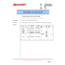
1. MAJOR FUNCTIONS
Configurations
Descriptions of items
Descriptions of items
F
: Standard provision
×
: No function or no option available
Item
CPM
SB/MB
2 Tray
SPF
R-SPF
Color
Scanner
GDI
printer
PCL
printer
SOPM
Duplex
Memory
FAX
Model
AL-1552
15CPM
SB
×
×
×
F
F
×
F
F
16M
×
AL-1553
15CPM
MB
×
F
×
F
F
×
F
F
16M
×
CPM:
Copy speed (Copies Per Minute)
SB/MB:
SB = Manual feed single bypass, MB = Manual feed multi bypass
2 tray:
Second cassette unit.
SPF:
Original feed unit
R-SPF:
Duplex original feed unit
Color scanner:
Color scanner function
GDI printer:
GDI printer function with USB.
PCL printer:
PCL printer function with USB.
SOPM:
Scan Once Print Many function (Many copies are made by one scan.)
Duplex:
Auto duplex copy function
Memory:
Standard page memory
FAX:
FAX function.
AL-1553
AL-1552
AL-1552/AL-1553
DUPLEX-RELATED ITEMS
1 – 2
[ 2 ] DUPLEX-RELATED ITEMS
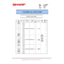
1. Motors and solenoids
No.
Part name
Control signal
Function/Operation
1
Main motor
MM
Drives the copier.
2
Scanner motor
MRMT
Drives the optical mirror base (scanner unit).
3
Toner motor
TM
Supplies toner.
4
Cooling fan motor
VFM
Cools the optical section.
5
Resist roller solenoid
RRS
Resist roller rotation control solenoid
6
Paper feed solenoid
CPFS1
Cassette Paper feed solenoid 1
7
Multi paper feed solenoid
MPFS
Multi manual pages feed solenoid
8
SPF motor
SPFM
Drives the single pass feeder
9
Duplex motor
DMT
Devices the duplex paper transport section
10
Original feed solenoid
SPUS
Original feed solenoid
11
Paper feed solenoid
CPFS2
Cassette Paper feed solenoid 2
12
SPF resist roller solenoid
SRRS
Original resist roller solenoid
13
SPF paper feed solenoid
SPFS
Original paper feed solenoid
3
9
2
13
8
12
10
4
1
5
7
11
6
AL-1552/AL-1553
DUPLEX-RELATED ITEMS
1 – 3
2. Duplex motor section (Duplex model only)
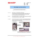
A. Remove the rear cabinet.
1) Remove four screws.
2) Remove the rear cabinet.
B. Remove the main PWB.
1) Disconnect each connector.
2) Remove four screws, and remove the MCU PWB.
3) Disconnect the connector.
4) Remove five screws, and remove the I/F PWB.
C. Remove the Duplex motor.
1) Remove two screws.
2) Remove the Duplex motor cover.
3) Remove the Duplex motor.
Note: When reassembling, be sure to engage the Duplex motor gear
with the belt on the main body side.
3. Reverse roller section (Duplex model only)
A. Remove the reverse unit.
1) Remove four screws.
2) Remove the spring, and the earth wire.
3) Remove the reverse unit.
B. Remove the reverse roller.
1) Bend the reverse roller and remove it.
1)
1)
1)
1)
1)
1)
1)
1)
2)
2)
2)
3)
1)
1)
2)
2)
2)
1
2
3
1
1
2
3
1
AL-1552/AL-1553
DUPLEX-RELATED ITEMS
1 – 4
4. Duplex adjustment
A. Adjusting the paper reverse position in memory
for duplex copying
This step adjusts the front surface printing (odd-number pages of a doc-
ument set) in the S-D mode copying and the leading edge position of an
image on even-number pages in the D-S mode.
That is, it covers the adjustment of the second surface printing mode
That is, it covers the adjustment of the second surface printing mode
(image loss at the front edge of an image) in which image data is once
stored in memory.
The image data is read, starting from its front end in the document deliv-
The image data is read, starting from its front end in the document deliv-
ery direction (Reference direction of document setting in the OC
mode)and stored in memory.
This stored image data is printed starting at the printing start position, in
This stored image data is printed starting at the printing start position, in
the order of last-stored data to the first-stored data.
In other words, the front edge image loss of the image can be adjusted
by changing the document read end position.
by changing the document read end position.
(Adjustment procedure)
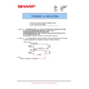
1) Preparing test chart (Draw a scale at the rear end of one side of a
sheet of A4 white paper or letter paper).
2) Set the test chart so that the scale is positioned as shown below,
in the S-D mode.
3) Execute simulation 50-18 to make a copy and check the front edge
image loss at the area where the scale is printed.
Adjust the setting so that the front edge image loss is less than 4.0
mm in the Duplex mode.
An increase of 1 in setting represents an increase of 0.1 mm
An increase of 1 in setting represents an increase of 0.1 mm
in image loss.
B. Adjusting trailing edge void in duplex copy mode
This is the adjustment of the first surface printing mode (rear end void)
in duplex copying.
In a duplex copying operation, the paper is delivered starting from the
rear end of the first printing surface. It is therefore necessary to make a
void area at the rear end on the first printing surface to prevent paper
jam at the fusing part.
Adjustment modes:
in duplex copying.
In a duplex copying operation, the paper is delivered starting from the
rear end of the first printing surface. It is therefore necessary to make a
void area at the rear end on the first printing surface to prevent paper
jam at the fusing part.
Adjustment modes:
1) Paper trailing edge void quantity 50-19 (TEXT)
This adjustment is made when the cassette paper size is recog-
nized. The trailing edge void quantity can be adjusted by changing
nized. The trailing edge void quantity can be adjusted by changing
the trailing edge image laser OFF timing.
(Adjustment procedure)
(1) Paper trailing edge void quantity
(1) Paper trailing edge void quantity
1) Preparing test chart (Draw a scale at the rear end of one side of a
sheet of A/4 white paper or letter paper)
2) Set the test chart on the document glass as shown below.
3) Using the user simulation [18], set the paper size of the first cassette.
4) Execute simulation 50-19 to turn on the TEXT lamp and make the
printing mode in OC-D mode.
Make a copy of the test chart to check the void area of the scale on
the image.
Make a copy of the test chart to check the void area of the scale on
the image.
Adjust the setting so that the void area is 4 - 5 mm. An increase in 1
of setting represents 0.1 mm in void area.
of setting represents 0.1 mm in void area.
5 10
Scale (S-D mode)
5 10
The front edge of the
scale on test chart
Front edge of paper
Void area
less than 4 mm
• Letter paper
: 4
• A4 paper
: 3
2nd printing surface where scale is printed (lower side)
Document guide
The trailing edge has a scale
Table glass
The trailing edge void on the first printing surface is shown above.
Paper
Void position to be check

