Sharp AL-1255 (serv.man12) Service Manual ▷ View online
AL-1555 SIMULATION, TROUBLE CODES 10 - 13
50
10
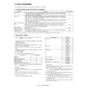
Center offset adjustment
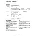
Used to adjust the copy image position on the copy paper and the center offset position when scanning a document.
(Operating procedure)
When this simulation is executed, the current setup value is displayed. Enter the adjustment value with the 10-key and press the PRINT
switch, and the entered value will be saved and a copy will be made. When the clear key is pressed, the entered value will be saved
and the simulation will be terminated. (When the setup value is increased by 1, shift is increased by 0.1mm.)
∗
When the setup value is too great, outside of the shading area may be read, and black streaks may be produced on the edges.
When the adjustment value is increased, the image is shifted to the left.
When the adjustment value is decreased, the image is shifted to the right.
When the adjustment value is increased, the image is shifted to the left.
When the adjustment value is decreased, the image is shifted to the right.
18
Memory reverse position adjustment in duplex copy
When this simulation is executed, the current setup value of correction is displayed. Enter the correction value with the 10-key and
press the PRINT switch, and the entered value will be saved. (Correction value 1 – 99, correction zero = 0, or 50) When the correction
value is set to 0, the correction value is written as 50.
Front surface printing in the S-D mode and printing on even pages in the D-S mode are reverse memory copy operations from the
document rear edge section.
When, therefore, the output image print position adjustment is required, adjust as follows:
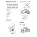
In the reverse memory copy operation, if the document scan direction is in the direction of the arrow in the figure, the scan rear edge
section of the image is printed first.
When, therefore, the print lead edge is shifted, set the reference chart so that the reference position is in the rear edge section, and use
this simulation to adjust so that the print image lead edge comes to the lead edge.
Since printing is performed by processing the scanned image from the scan end position to the scan lead edge, the print lead edge
position adjustment is performed by changing the end data position stored in memory with the simulation setup value.
19
Duplex copy rear edge void adjustment
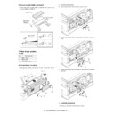
Used to adjust the rear edge void quantity in duplex copy.
(Operating procedure)
When this simulation is executed, the current setup value is displayed the current setup value is displayed in two digits. (Center value:
50 However, setup 50 = setup 0) When the correction value is set to 0, the correction value is written as 50. Press the copy mode select
key to select your desired copy mode, and the display will change. Enter the adjustment value with the 10-key and press the PRINT
switch, and the setup value will be saved and a copy will be made. (The paper information is cleared for every copying.) Press the clear
key to save the setup value and exit from the simulation mode. (Increasing the setup value by 1 increases the void quantity by about
0.1mm.)
Main
code
code
Sub
code
Content
: Supported only for installing models, and skipped for not-installing models.
Adjustment mode
Lamp ON
Print center offset (Main cassette paper feed)
AE, main cassette lamp
Print center offset (2nd cassette paper feed)
AE, 2nd cassette lamp
Print center offset (Manual paper feed)
AE, manual paper feed lamp
OC/document center offset
AE, TEXT lamp
SPF/RSPF (front) document center offset
AE, TEXT, PHOTO lamp
Print lead edge
Lead edge void (1)
Print start position
Lead edge void (1)
Print start position
Rear edge void
Print rear edge
Print rear edge
Document transport direction
Scan lead edge
Scan end position
(Default: Scan cut by void (1))
(Default: Scan cut by void (1))
Scan direction
Scan rear edge
Paper transport direction
Adjustment mode
Lamp ON
Image cut rear edge void quantity (RSPF)
AE lamp
Paper rear edge void quantity
TEXT lamp
Print start position (Duplex back)
PHOTO lamp
RSPF (Back) original center offset
AE, TEXT, PHOTO lamps
AL-1555 SIMULATION, TROUBLE CODES 10 - 14
51
02
Resist quantity adjustment
Used to adjust the contact pressure of paper against the machine resist roller and the RSPF resist roller.
(Operating procedure)
When this simulation is executed, the current setup value is displayed.
Enter the adjustment value with the 10-key and press the PRINT switch, the entered set value will be saved and a copy will be made.
When the clear key is pressed, the entered value will be saved and the machine will exit from the simulation mode.
53
08
SPF scan position automatic adjustment
Place a black chart so that it covers the SPF scan glass and the OC glass, and execute the simulation with the OC cover open, the
mirror unit scans from the home position to the SPF scan position to identify the SPF glass cover edge position by the difference in the
CCD output levels of the SPF glass cover edge and the OC side document glass.
Default is 50. Adjustment range is 0 – 99. Adjustment increment: 1 = about 0.127mm
If this adjustment is performed properly, the adjustment value is displayed. If it is abnormal, the jam lamp lights up. If the adjustment is
not made properly, “– –” is displayed.
61
03
Polygon motor check (HSYNC output check)
(Operation/Procedure)
When the START key is pressed, HSYNC is performed and the polygon motor is rotated for 30 sec.
At that time, the Zoom lamp is lit for 100msec for every 3 times that the HSYNC is detected.
(Operation/Procedure)
When the START key is pressed, HSYNC is performed and the polygon motor is rotated for 30 sec.
At that time, the Zoom lamp is lit for 100msec for every 3 times that the HSYNC is detected.
63
01
Shading check
Used to display the detection level of the white board for shading.
(Operating procedure)
When the PRINT switch is pressed, the mirror base unit moves to the white board for shading to light the copy lamp. Under this state,
the level of one pixel at the CCD center which is not corrected for 10sec in 1 sec, and the result is displayed on the value display
section.
64
01
Self print
Print of one page is made regardless of the status of the optical system.
(Operating procedure)
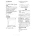
When this simulation is executed, warm-up is performed and the ready lamp is lighted. Enter the code number with the 10-key, and
select the cassette with the cassette select key and press the PRINT switch, and paper feed operation will be made from the selected
cassette and printing of the selected pattern will be made. Printing is in 1by2 mode, or grid pattern.
Main
code
code
Sub
code
Content
: Supported only for installing models, and skipped for not-installing models.
Adjustment mode
Lamp ON
Main cassette paper feed
AE, main cassette lamp
2nd cassette paper feed
AE, 2nd cassette lamp
Manual paper feed
AE, manual paper feed lamp
RSPF document feed (front)
AE, TEXT, PHOTO lamp
RSPF document feed (back)
AE, TEXT lamp
duplex back
TEXT, PHOTO lamp
∗
2 – 99: print in 1by2.
Code number
Pattern
0
1by2
1
Grid pattern
AL-1555 SIMULATION, TROUBLE CODES 10 - 15
4. Trouble codes
A. Trouble codes list
Main
code
code
Sub
code
Trouble content
Detail of trouble
E7
01
Duplex model memory
setup error, memory not-
detected error
setup error, memory not-
detected error
The memory is not set properly or the memory capacity is not set to the duplex setup (6M).
Cancel method: Set SIM 26-39 code number to 2.
Cancel method: Set SIM 26-39 code number to 2.
02
HSYNC not detected.
LSU (laser diode, reception element, APC circuit) trouble
LSU drive circuit (ASIC) trouble
LSU drive circuit (ASIC) trouble
10
CCD black level trouble
CCD drive circuit (CCD PWB, ASIC, harness) trouble
11
CCD white level trouble
CCD drive circuit (CCD PWB, ASIC harness) trouble
Copy lamp lighting trouble (Copy lamp, inverter PWB)
Copy lamp lighting trouble (Copy lamp, inverter PWB)
12
Shading trouble
(White correction)
(White correction)
Dirt on white plate for scanning white level
16
Laser output trouble
LSU (laser diode, reception element, APC circuit) trouble
LSU drive circuit (ASIC) trouble
LSU drive circuit (ASIC) trouble
F5
02
Copy lamp disconnection
trouble
trouble
Copy lamp or copy lamp drive circuit (inverter PWB) trouble
Copy lamp disconnection
Copy lamp disconnection
H2
00
Thermistor open detection The fusing thermistor is open.
H3
00
Heat roller abnormally high
temperature
temperature
The fusing temperature rises above 240° C.
H4
00
Heat roller abnormally low
temperature
temperature
The fusing temperature does not reach 185° C within 27 sec of turning on the power, or the fusing
temperature keeps at 140° C.
temperature keeps at 140° C.
L1
00
Feeding is not completed
within the specified time
after starting feeding.
(The scan head locking
switch is locked)
within the specified time
after starting feeding.
(The scan head locking
switch is locked)
The white area and the black marking on the shading plate are used to obtain the difference in the CCD
level values for judgment of lock. When the difference in the levels of which and black is small, it is judged
that the black mark could not be scanned by lock and the trouble code “L1” is displayed.
level values for judgment of lock. When the difference in the levels of which and black is small, it is judged
that the black mark could not be scanned by lock and the trouble code “L1” is displayed.
L3
00
Return is not completed
within the specified time.
within the specified time.
When the mirror base is returned for the specified time (6 sec) in mirror initializing after turning on the
power, the mirror home position sensor (MHPS) does not turn ON. Or when the mirror base is returned for
the specified time (about 6 sec) after start of copy return, the mirror home position sensor (MHPS) does not
turn ON.
power, the mirror home position sensor (MHPS) does not turn ON. Or when the mirror base is returned for
the specified time (about 6 sec) after start of copy return, the mirror home position sensor (MHPS) does not
turn ON.
L4
01
Main motor lock
When the main motor encoder pulse is not detected for 100 msec.
L6
10
Polygon motor lock
The lock signal (specified rpm signal) does not return within a certain time (about 20 sec) from starting the
polygon motor rotation
polygon motor rotation
U2
01
Counter sum check error
04
EEPROM serial
communication error
communication error
When a communication trouble occurs with the EEPROM.

