Sharp AL-1217 (serv.man11) Service Manual ▷ View online
AL-1226 DISASSEMBLY AND ASSEMBLY 8 - 8
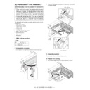
5) Remove the PWB insulation mylar and remove the paper transport
detection sensor (PPD2).
6) Remove two screws and remove the toner motor.
7) Remove two springs and open the intermediate frame unit.
8) Remove the pulleys on the both sides and remove the paper exit
roller.
2)
1)
3)
1)
2)
1)
2)
4)
2)
1)
3)
AL-1226 DISASSEMBLY AND ASSEMBLY 8 - 9
9) Pull out the paper exit roller knob and remove the belt.
10) Release the belt pulley (a) lock and remove the belt pulley bearing.
11) Remove the paper exit roller.
12) Remove the harness guide.
1)
2)
2)
3)
1)
AL-1226 DISASSEMBLY AND ASSEMBLY 8 - 10
13) Remove five screws and remove the main drive plate and the belt.
14) Remove the parts as shown below, and remove the pressure
release solenoid and the paper feed solenoid.
15) Remove six screws and remove the LSU unit.
The scan inclination classification is indicated on the right or the
left of the LSU production number label according to the classifica-
tion.
left of the LSU production number label according to the classifica-
tion.
When replacing the LSU, add the spacer according to the scan
inclination classification. (The spacer is packed together with every
LSU.)
inclination classification. (The spacer is packed together with every
LSU.)
Scan inclination classification check
Scan inclination classification 1: +0.26 – + 0.5 (White marking on
the right of the production number label)
the right of the production number label)
Scan inclination classification 2: – 0.25 – +0.25 (White marking)
Scan inclination classification 3: – 0.5 – – 0.26 (White marking on
the left of the production number label)
the left of the production number label)
1)
3)
2)
1)
CAUTION:Attach the gears securely
3)
3)
1)
1)
2)
2)
4)
4)
1)
1)
2)
LSU spacer not required
Machine rear side
Add one LSU spacer.
Add one LSU spacer.
Machine front side
Add one LSU spacer.
Add one LSU spacer.
AL-1226 DISASSEMBLY AND ASSEMBLY 8 - 11
Addition of the spacer
Scan inclination classification 1: Add the LSU spacer to the rear
side of the machine.
side of the machine.
Scan inclination classification 2: No need to add the spacer.
Scan inclination classification 3: Add the LSU spacer to the front
side of the machine.
side of the machine.
[Note for assembling the LSU]
When installing the LSU, turn the LSU clockwise and fix with
screws in order to provide an attachment backlash in the proper
direction.
screws in order to provide an attachment backlash in the proper
direction.
Observe the following sequence of fixing screws.
16) Remove each pawl, and remove the paper exit tray.
Insert into the
positioning boss.
positioning boss.
Fit the holes and attach.
<Machine rear side>
Machine front side
Insert into the
positioning boss.
positioning boss.
Fit the holes and attach.
<Machine front side>
1
3
5
2
4
6
2)
1)
3)
Click on the first or last page to see other AL-1217 (serv.man11) service manuals if exist.

