Sharp AL-1217 (serv.man11) Service Manual ▷ View online
AL-1226 DISASSEMBLY AND ASSEMBLY 8 - 2
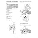
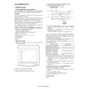
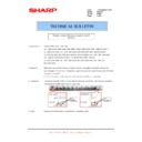
2) Set the charger cleaner to the transfer unit, and move it recipro-
cally a few times in the direction of the arrow shown in the figure
below.
below.
E. Charger wire replacement
1) Remove the TC cover and remove the screw.
2) Remove the spring and remove the charger wire.
3) Install a new charger wire by reversing the procedures (1) and (2).
At that time, be careful of the following items.
• The rest of the charger wire must be within 1.5mm. Refer to Fig.1
• The spring hook section (charger wire winding section) must be in
the range of the projection section.
• Be careful not to twist the charger wire.
2. Operation panel section
A. List
B. Disassembly procedure
1) Open the side door, and Open the front cover.
2) Remove the screws (4 pcs.), the harness, and the operation panel
unit.
1)
2)
3)
4)
1mm
1.5mm
Fig.1
1)
1)
2)
3)
Charger wire
Protrusion
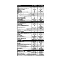
No.
Part name Ref.
1
Operation panel unit
2
Operation PWB
1)
2)
1)
1)
1)
1)
2)
3)
AL-1226 DISASSEMBLY AND ASSEMBLY 8 - 3
3) Remove four screws, and remove the operation cabinet.
4) Remove four screws, and remove the operation PWB.
C. Assembly procedure
For assembly, reverse the disassembly procedure
3. Optical section
A. List
B. Disassembly procedure
1) Remove four screws, and remove the rear cabinet and the rear
cabinet cover.
2) Remove the connector and the clamp, and remove the SPF unit.
3) Remove the four screws, remove the operation unit, and discon-
nect the connector.
4) Remove the right cabinet.
5) Remove the left cabinet.
6) Remove the screw, and remove the rear cover.
7) Remove the table glass.
NO.
Part name Ref.
1
Copy lamp unit
2
Copy lamp
3
Lens unit
1)
1)
1)
1)
2)
3)
3)
3)
4)
Note that there are 10 pawls
2)
1)
1)
1)
1)
3)
5)
4)
1)
2)
1)
1)
2)
4)
5)
6)
7)
8)
1)
1)
3)
AL-1226 DISASSEMBLY AND ASSEMBLY 8 - 4
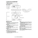
8) Move the carriage to the position indicated on the figure.
9) Loosen the screw which is fixing the tension plate.
10) Move the tension plate in the arrow direction to release the ten-
sion, and remove the belt.
11) Remove the screw, and remove the rod stopper.
12) Remove the rod.
13) Lift the rear side of the carriage, remove the belt and the connec-
tor, and remove the carriage.
C. Assembly procedure
CCD core
1) Pass the core through the CCD-MCU harness.
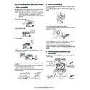
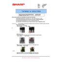
2) Insert the CCD-MCU harness into the CCD PWB connector of the
carriage unit.
3) Move the core which was passed through the CCD-MCU harness
near the CCD PWB connector as shown in the figure below, and fix
it with a filament tape (19mm wide, 40mm long). For the attach-
ment reference, refer to the figure below. Clean and remove oil
from the attachment section.
it with a filament tape (19mm wide, 40mm long). For the attach-
ment reference, refer to the figure below. Clean and remove oil
from the attachment section.
4) Attach the CCD-MCU harness to the duplex tape on the back of
the carriage unit.
5) Attach the PWB holder to the position specified in the figure below.
6) Pass the core through the FFC and the PWB holder, and fix the
core.
1)
2)
4)
3)
1)
2)
3)
1)
2)
4)
3)
Marking line
Note: Attach the FFC
to fit with the marking line.
to fit with the marking line.
Note: Attach the FFC to the base
plate securely with duplex tape to
prevent against coming loose.
plate securely with duplex tape to
prevent against coming loose.
AL-1226 DISASSEMBLY AND ASSEMBLY 8 - 5
4. Fusing section
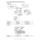
A. List
B. Disassembly procedure
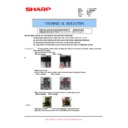
1) Remove the connectors (3 pcs.) of the rear cabinet.
2) Open the side cover, remove two screws, and remove the fusing
unit.
3) Cut the binding band, remove the screw, and remove the ther-
mistor.
4) Remove the screw and remove the U-turn guide.
Pressure roller section disassembly
5) Remove the three screws, remove the fusing cover lower on the
right side, and open the heat roller section.
6) Remove the screw and remove the PPD2 sensor.
No.
Part name Ref.
1
Thermistor
2
PPD2 sensor
3
Heater lamp
4
Pressure roller
5
Heat roller
1)
2)
3)
2)
1)
2)
3)
Thermistor
1)
2)
1)
5)
5)
6)
6)
4)
3)
2)
1)
2)
PPD2 sensor

