Sharp AL-1045 (serv.man9) Service Manual ▷ View online
AL-1555 DISASSEMBLY AND ASSEMBLY 8 - 21
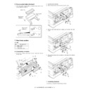
G. Paper entry sensor
1) Loosen the screw.
2) Open the paper exit paper guide.
3) Remove the paper entry sensor.
4) Remove the harness.
H. PS roller
1) Remove the parts.
2) Remove the paper supply roller.
I. Paper exit roller
1) Remove the parts.
2) Remove the paper exit roller.
10. 2nd cassette section
Paper feed unit removal
1) Remove the screw.
2) Remove the rear cover.
* When installing, engage the pawl and install the unit.
1
4
2
3
1
1
2
1
2
1
No.
Part name Ref.
A
Paper sensor
B
Cassette detection SW
C
Paper feed solenoid
D
Transport roller
E
Paper feed clutch
F
2nd paper feed roller
2)
1)
1)
1)
1)
1
2
A
AL-1555 DISASSEMBLY AND ASSEMBLY 8 - 22
1) Open the right cabinet.
2) Remove three screws.
3) Remove one connector from MCU.
4) While tilting down the 2nd connection arm A, pull and remove the
paper feed unit toward you.
* When installing, securely insert two bosses C on the machine side
and two bosses D on the paper feed unit side. Be sure to secure the
ground wire B.
ground wire B.
* Insert the 2nd page feed.
A. Paper sensor
1) Remove the pawl.
2) Remove the paper sensor.
3) Remove the harness.
B. Cassette detection switch
1) Remove the pawl.
2) Remove the cassette detection switch.
3) Remove the harness.
C. Paper feed solenoid
1) Remove the screw.
2) Remove the connector.
3) Remove the paper feed solenoid.
D. Transport roller
1) Remove two E-rings.
2) Remove the transport roller.
* Install so that the earth spring A is brought into contact over bearing
B.
1
2
4
B
A
3
2
D
D
C
2
3
1
1
2
3
1
2
3
4
2
1
3
A
B
AL-1555 DISASSEMBLY AND ASSEMBLY 8 - 23
E. Paper feed clutch
1) Remove the E-ring.
2) Remove the paper feed clutch.
3) Remove the parts.
* When installing, fit the cut surface A.
F. 2nd paper feed roller
1) Remove the E-ring and the parts.
2) Remove the 2nd paper feed roller.
* When installing, hang the 2nd connection arm on the 2nd connection
arm Spring B. Be sure to install so that the earth spring C is in
contact under the bearing D.
contact under the bearing D.
11. Duplex motor section (RSPF model
only)
A. Remove the rear cabinet.
1) Remove four screws.
2) Remove the rear cabinet.
B. Remove the main PWB.
1) Disconnect each connector.
2) Remove four screws, and remove the MCU PWB.
3) Disconnect the connector.
4) Remove five screws, and remove the I/F PWB.
A
1
2
3
B
1
2
1
C
D
A
1)
1)
1)
1)
1)
1)
1)
1)
2)
2)
2)
3)
1)
1)
2)
2)
2)
AL-1555 DISASSEMBLY AND ASSEMBLY 8 - 24
C. Remove the Duplex motor.
1) Remove two screws.
2) Remove the Duplex motor cover.
3) Remove the Duplex motor.
Note: When reassembling, be sure to engage the Duplex motor gear
with the belt on the main body side.
12. Reverse roller section (RSPF model
only)
A. Remove the reverse unit.
1) Remove four screws
2) Remove the spring, and the earth wire
3) Remove the reverse unit.
B. Remove the reverse roller.
1) Bend the reverse roller and remove it.
13. RSPF section (RSPF model only)
A. RSPF
(1) Remove the rear cabinet.
1) Remove four screws.
2) Remove the rear cabinet.
(2) Remove the RSPF.
1) Remove the connector and the cable.
2) Remove the RSPF.
B. Intermediate tray
1) Remove the intermediate tray.
1
2
3
1
1
2
3
1
1
2
1
Click on the first or last page to see other AL-1045 (serv.man9) service manuals if exist.

