Sharp PN-V602 (serv.man7) Service Manual ▷ View online
CHAPTER 8. HARDWARE DESCRIPTIONS
PN-V602 HARDWARE DESCRIPTIONS
8 – 3
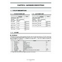
■ COIN BATTERY
1 - 5. LED-TCON PWB
Description
1
Function of coin battery
It acts as a backup battery for clock when the display main power is powered off.
2
Failure phenomenon when the battery
becomes exhausted
becomes exhausted
The time is cleared while the display main power is off, and the time setting window of OSD
is displayed when the main power is turned on.
is displayed when the main power is turned on.
3
PWB supply
It is supplied with the coin battery installed.
4
Voltage that can be judged as battery
exhaustion
exhaustion
The clock can run when the voltage is 2.0V or more.
5
Usable years
The coin battery life is designed to be about 8 years.
Since the estimated product life is 5 years, the coin battery does not need to be replaced.
Therefore, it is not listed as a consumable part in the parts guide.
Therefore, it is not listed as a consumable part in the parts guide.
Parts Name
Location
Manufacture
Parts Number
Function
Remark
Sub microprocessor
IC6
Renesas
uPD78F1165AGC(S)-
UEU-AX
UEU-AX
Microprocessor for LED-TCON
Performs LED-TCON boot sequence
control, IRIS/LED driver parameter
control, IRIS/LED driver parameter
setting, detection and notification of
error information (LED open, short,
temperature, other LED-TCON
temperature, other LED-TCON
errors).
IRIS
IC3
sharp
IRIS
Controller to realize the LED area
active backlight technology for WXGA
Performs through I2C interface control
from the sub microprocessor and boot
setting from the serial memory of SPI
setting from the serial memory of SPI
interface.
FPGA
IC7
Altera
EP3C16E144C8N
Interfaces communication between
LED-TCON (FPGA) and IRIS and
LED driver (iWatt iW7032).
Interfaces communication between
the sub microprocessor and LED
the sub microprocessor and LED
driver for various setting and status
data.
Interfaces LED brightness data
between IRIS and LED driver and per-
between IRIS and LED driver and per-
forms transmission.
CONFIG DEVICE
IC9
Altera
EPCS4SI8N
Configuration ROM for FPGA
Stores the configuration data by using
SRAM cell.
2Mb Serial FLASH
IC1
ATMEL
AT25DF021-SSH-T
SPI Serial ROM for IRIS
Performs boot setting and stores LUT
parameters.
parameters.
64Mb Serial
EEPROM
EEPROM
IC15
Rohm
BR24T64F-WE2
I2C EEPROM for FPGA
Stores the lighting timing data of LED
driver.
driver.
Stores boot setting and LUT parame-
ters.
DA converter
IC12
Rohm
Not installed
(BH2228FV)
6ch DA converter.
Controls the voltage value (20V 3ch,
27V 3ch) applied to the LED PWB by
control of the LED microprocessor.
CHAPTER 8. HARDWARE DESCRIPTIONS
PN-V602 HARDWARE DESCRIPTIONS
8 – 4
DA converter
IC13
Rohm
Not installed
(BH2228FV)
6ch DA converter
Controls the voltage value (20V 3ch,
27V 3ch) applied to the LED PWB by
control of the LED microprocessor.
control of the LED microprocessor.
Switching regulator
IC2
Semtech
SC4525CSETRT
Switching regulator
(12V
(12V
33.3V generation)
Switching regulator
IC4
Semtech
SC4525CSETRT
Switching regulator
(12V
(12V
31.2V generation)
Voltage regulator
IC5
Richo
RP130N251B-TR-FE
LDO regulator
(3.3V
(3.3V
32.5V generation)
General-use logic
IC8
TOSHIBA
TC7PA17FU
2ch Schmidt-buffer IC
General-use logic
IC10,14
TOSHIBA
TC74HC4066AFT
Analog switch
Voltage regulator
IC11
Richo
N.M.(R1190S050D-E2-
FE)
LDO regulator
(12V
35V generation)
Reset IC
IC500
Rohm
BD45285G-TR
Reset IC
Chip LED
LED1
LITEON
Not installed
(LTST-
(LTST-
C190KGKT(1608))
Lights up when in IRIS SYNC_ERR.
Chip LED
LED2
LITEON
LTST-C190KGKT(1608) Flashes in case of errors.
41Pin LCD/IF/LED
connector
connector
CN6
HIROSE
FX16S-41S-0.5SH
LVDS image from MAIN IF PWB/ Sig-
nal input connector
nal input connector
18Pin IF connector
CN7
JST
S18B-PUDSS-
1(LF)(SN)
1(LF)(SN)
Signal input connector from MAIN IF
PWB
PWB
Power connector
CN5
JST
SM07B-PASS-
TBT(LF)(SN)
TBT(LF)(SN)
Power 12V input connector
LED power 4Pin con-
nector
nector
CN15
JST
Not installed
(BM12B-GVHS-TB)
(BM12B-GVHS-TB)
Analog output connector to LED
power
power
LED power 4Pin con-
nector
Abolished
Analog output connector to LED
power
LED power 4Pin con-
nector
CN9
JST
Not installed
(BM04B-GVHS-TB)
Analog output connector to LED
power
41Pin LCD/IF/LED
connector
CN3
HIROSE
FX16S-41S-0.5SH
LVDS image to LCD-TCON PWB/Sig-
nal output connector
LCD-TCON power
4Pin connector
CN1
JST
SM04B-PASS-
TBT(LF)(SN)
Power output connector to LCD-
TCON PWB
41Pin LCD/IF/LED
connector
CN8
JST
SM30B-SHLDS-G-TF
LED-DRIVER control signal output to
LED-DRIVER PWB, PD input and TH
input connector
input connector
X_4Pin connector
CN14
Not installed
(B4B-ZR-3.4)
(B4B-ZR-3.4)
Serial connector for debug
X_4Pin connector
CN12
Not installed
(B4B-ZR-3.4)
(B4B-ZR-3.4)
I2C connector for debug
X_4Pin connector
CN2
Not installed
(B7B-ZR-3.4)
(B7B-ZR-3.4)
Connector for debug
X_4Pin connector
CN11
Not installed
(B7B-ZR-3.4)
(B7B-ZR-3.4)
FPGA Config ROM writing connector
X_8Pin connector
CN4
Not installed
(B8B-ZR-3.4)
(B8B-ZR-3.4)
SPI Serial ROM writing connector for
IRIS
IRIS
X_8Pin connector
CN13
Not installed
(B8B-ZR-3.4)
(B8B-ZR-3.4)
Connector for QB-MINI2
X_9Pin connector
CN10
Not installed
(B9B-ZR-3.4)
(B9B-ZR-3.4)
I2C EEPROM writing connector for
FPGA
FPGA
Parts Name
Location
Manufacture
Parts Number
Function
Remark
CHAPTER 8. HARDWARE DESCRIPTIONS
PN-V602 HARDWARE DESCRIPTIONS
8 – 5
1 - 6. LED DRIVER PWB
■ MAIN COMPLETE PARTS AND FUNCTION
1 - 7. KEY PWB
■ MAIN COMPLETE PARTS AND FUNCTION
1 - 8. EXPANSION BOARD
■ I/O SIGNAL
*
1
The setting of terminals needs to be configured in the terminal selection menu.
■ MAIN COMPLETE PARTS AND FUNCTION
Reference
Parts name
Functions
IC4,IC5,IC12,IC13,IC18,IC19,IC23,IC24,IC25,
IC30,IC31,IC39
IC30,IC31,IC39
iW7032S
(LED Drv IC)
Controls PWM the LED.
Controls PWM the LED.
IC1,IC2,IC3,IC6,IC9,IC10,IC14,IC15,IC16,
IC17,IC20,IC21,IC22,IC26,IC27,IC28,IC29,
IC17,IC20,IC21,IC22,IC26,IC27,IC28,IC29,
IC32,IC33,IC34,IC35,IC36,IC37,IC38
BD9306AFVM
(DC/DC)
Boosted from 24V, and generates the LED
Boosted from 24V, and generates the LED
applying voltage.
IC7,IC8
TC74VHC138FT
(Decoder)
IC11
SN74LVC244APW R
(BUFFER)
Reference
Part/Type name
Part function
D101
SML-022ML8T
LED
SW101, SW102,
SW103, SW104,
SW103, SW104,
SW105, SW106,
SW107
SKRPABE010
Switch
Specifications
Connector used
PC signal
Digital video input terminal (DVI-compliant)
DVI-D terminal
*1
Digital video output terminal (for daisy chaining)
DVI-D terminal
Analog video input terminal
BNC x 5
*1
AV signal
Digital video input terminal
DVI-D terminal
Composite video input terminal
BNC x 1
Component video input terminal
BNC x 3
*1
S terminal
S terminal
Audio signal
Audio input terminal for AV devices
RCA (R) (L) x 2
Speaker output
Support for 6
Ω speaker
Speaker terminal
Reference
Part name
Part function
IC201
SiI9135ACTU
HDCP compliant DVI receiver.
IC302, IC305
SiI9134CTU
DVI transmitter, used to transmit video data from extension side to main side.
IC204
R1EX24002ASAS0A
I
2
C compliant EEPROM, stores EDID data for HDMI.
Write-protect can be released from service menu.
IC401
MCF52258AG80
Microcontroller for LAN control.
Once this microcontroller is replaced, the firmware/ MAC address is cleared.
Since the MAC address is not allowed to be written on the occasion of ser-
vice, it is not established as a service part.
vice, it is not established as a service part.
IC402
CS18LV20483EIR55
SRAM, used as RAM for the microcontroller of LAN control.
IC403
RTL8201EL-GR
Ethernet PHYCEIVER
IC408
SC16IS750IPW
I
2
C · EUART, used for communication with the main scaler.
IC502
STA333W
Digital audio amplifier with the expansion board connected.
IC203, IC304
S-1132B33-M5T1G
Regulator, generates various kinds of voltages.
IC205, IC306
PQ018ENAZ1PH
IC501
PQ1LA335
CHAPTER 8. HARDWARE DESCRIPTIONS
PN-V602 HARDWARE DESCRIPTIONS
8 – 6
1 - 9. PWB OF CONTROL KIT
■ I/O SIGNAL
■ MAIN COMPLETE PARTS AND FUNCTION
Specifications
Connector used
Control Signal
Control Kit control input/output terminal
3pin connector (The harness for connecting I/F board is connected on the
PWB.)
PWB.)
Reference
Part name
Part function
IC103
R5F21324CNSP
Micro computer (micom) Communicate with the micom on the I/F board, and
send the illumination sensor ADC value and remote control data.
IC105
GP1USC31XP
Photoreceiver for remote controller.
Receive the signal from the remote controller.
IC106
GA1A2S100LY
Illumination sensor.
Receive the light around the Control Kit (PN-ZR01).
IC101
TC7SH14FU
Schmitt trigger inverter
IC102
PQ1X301M2ZPH
Regulator.
Generate the ADC reference voltage of micom and illumination sensor.

