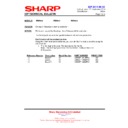
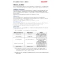
Sharp PN-S525 (serv.man4) Service Manual / Parts Guide ▷ View online
– 1 –
1
Exteriors
NO.
PARTS CODE
PRICE
RANK
NEW
MARK
PART
RANK
DESCRIPTION
1
G C A B A 1 0 4 4 M P Z Z
BC
D
Front bezel top
2
L A N G K 1 2 1 0 M P Z Z
AF
C
Bezel angle A
3
X U B S N 3 0 P 0 8 0 0 0
AA
C
Screw(3
×8)
4
G C A B A 1 0 4 6 M P Z Z
BA
D
Front bezel LR
5
G C A B A 1 0 4 5 M P Z Z
BC
D
Front bezel bottom
6
T L A B Z 1 5 7 9 M P Z Z
AK
D
SHARP logo label
7
L A N G K 1 2 1 1 M P Z Z
AF
C
Bezel angle B
8
P F I L W 1 0 1 1 M P Z Z
AH
D
IR filter
12
L A N G K 1 2 1 2 M P B Z
BG
N
C
Connecter panel
13
T L A B Z 1 8 0 2 M P Z Z
AN
N
D
I/F label B
14
P C U S S 1 0 4 1 M P Z Z
AD
C
Stand cover cushion
15
X B P S 8 3 0 P 0 8 K S 0
AB
C
Screw(3
×8KS)(Black)
16
T L A B Z 1 8 0 1 M P Z Z
AN
N
D
I/F label A
17
T L A B M 1 7 9 0 M P Z A
AS
N
D
Rating label
[PN-S525E]
T L A B M 1 7 9 0 M P Z Z
AS
N
D
Rating label
(Abolition in October, 2008 from 1st in production)[PN-S525U]
T L A B M 1 7 9 0 M P Z B
AS
N
D
Rating label
(Addition in October, 2008 from 1st in production)[PN-S525U]
18
L A N G T 1 2 3 6 M P A Z
BA
N
C
Stand cover
19
C C O V A 1 0 7 8 M P 0 2
CA
N
D
Rear cover A
20
J H N D P 1 0 0 1 M P Z Z
AQ
D
Handle
21
X B B S 8 6 0 P 2 0 0 0 0
AC
C
Screw(6
×20)
22
X B B S 8 6 0 P 1 0 0 0 0
AC
C
Screw(6
×10)
23
T L A B M 1 8 0 4 M P Z Z
AL
N
D
Rating label
[PN-S525E(China)]
– 2 –
1
Exteriors
TP000637
3
1
3
2
3
2
3
3
3
4
2
3
3
4
3
3
2
3
3
2
6
3
2
3
7
2
3
3
2
5
14
13
12
15
18
15
16
15
15
15
17
23
14
20
21
20
21
15
15
15
15
15
15
22
15
22
15
15
2
8
19
– 3 –
2
Internal mechanism
NO.
PARTS CODE
PRICE
RANK
NEW
MARK
PART
RANK
DESCRIPTION
1
X B P S 8 3 0 P 0 8 K S 0
AB
C
Screw(3
×8KS)(Black)
2
L A N G T 1 2 2 6 M P Z Z
BA
C
Frame TB F
4
P S H E Z 1 1 4 9 M P Z Z
AL
N
C
LCD protect sheet
5
V V L K 5 2 0 D 3 L A 1 9
FE
N
E
LCD(LK520D3LA19)
7
L A N G T 1 2 2 7 M P Z Z
BA
C
Fame side F
8
L H L D W 1 0 1 9 M P Z Z
AD
C
Clamp(RBWS-2M)
9
Q C N W - 1 3 9 2 M P Q Z
AR
N
C
Key cable
10
C P W B N 1 0 9 2 M P S 4
BF
N
E
52Key PWB unit
11
P T P E Z 1 0 3 1 M P Z Z
AB
D
Key fixing tape
12
L A N G K 1 2 0 9 M P Z Z
AG
C
Key angle
13
L H L D W 0 5 4 4 F C Z Z
AC
C
Harness clamp(FCA-10)
14
C A N G T 1 2 2 8 M P 0 2
BG
N
C
Frame top R
15
X B B S 8 6 0 P 1 0 0 0 0
AC
C
Screw(6
×10)
16
X B P S N 4 0 P 0 8 K S 0
AA
C
Screw(4
×8KS)(Silver)
18
C A N G T 1 2 3 0 M P 0 2
BG
N
C
Frame side R
19
Q S L P A 1 0 0 1 M P Z Z
AL
C
Gasket
20
X B P S N 3 0 P 0 8 K S 0
AA
C
Screw(3
×8KS)
21
L A N G T 1 2 3 3 M P Z Z
AZ
D
Bridge frame
23
P S H E Z 1 1 5 0 M P Z Z
AH
N
C
INV cable protect sheet
29
Q C N W - 1 3 9 0 M P Q Z
AS
N
C
INV cable 1
30
L A N G K 1 2 0 7 M P B Z
BN
N
D
Main frame
32
C P W B N 1 0 9 2 M P S 2
BE
E
Sensor 1 PWB unit
33
L H L D W 1 0 1 8 M P Z Z
AC
C
Cable holder(NPL-520V0)
35
L H L D W 6 6 5 5 R C Z Z
AB
C
Cable holder(LWS-2NS)
36
L H L D W 1 0 1 7 M P Z Z
AC
C
Cable holder(NPL-1230)
!
37
R U I T K 1 0 1 6 M P P Z
BE
E
PS filter PWB unit
38
Q C N W - 1 2 9 1 M P P B
AN
C
AC PS cable 1
!
39
R D E N C 1 0 1 0 M P P Z
CC
E
PS unit(Main)
40
Q C N W - 1 3 9 1 M P Q Z
AS
N
C
INV cable 2
41
Q C N W - 1 3 8 0 M P Q Z
AL
N
C
PS cable 1
42
Q C N W - 1 3 7 9 M P Q Z
BD
N
C
Inlet cable
43
P S H E Z 1 1 2 5 M P Z Z
AC
C
Part AC cover sheet
44
X B S S 8 3 0 P 0 6 0 0 0
AC
C
Screw(3
×6)
!
45
Q S W - C 1 0 1 2 M P P Z
AP
B
AC switch(AJ7201BF)
46
Q C N W - 1 3 8 2 M P Q Z
AL
N
C
PS cable 3
47
Q C N W - 1 3 8 1 M P Q Z
AL
N
C
PS cable 2
48
C P W B Y 1 0 9 1 M P S 2
CP
N
E
I/F1 PWB unit
49
Q C N W - 1 3 8 8 M P Q Z
AF
N
C
Temperature sensor cable 1
51
C P W B N 1 0 9 2 M P S 6
BE
N
E
Sensor 2 PWB unit
52
Q C N W - 1 3 8 6 M P Q Z
AQ
N
C
Temperature sensor cable 2
53
C P W B N 1 0 9 2 M P S 1
BR
E
I/F2 PWB unit
54
L A N G T 1 2 1 7 M P Z Z
AS
C
Top bridge
55
L A N G T 1 2 1 6 M P A Z
AX
C
VESA bridge
56
L A N G T 1 2 5 6 M P Z Z
AP
N
C
Connector angle
57
L X - B Z 1 0 0 3 M P Z Z
AE
C
Screw
58
X U B S N 3 0 P 0 8 0 0 0
AA
C
Screw(3
×8)
59
P S H E Z 1 1 3 0 M P Z Z
AE
C
Key sheet
60
C A N G T 1 2 2 9 M P 0 2
BG
N
C
Frame bottom
62
Q C N W - 1 3 8 9 M P Q Z
BD
N
C
LCD cable
63
Q C N W - 1 3 4 1 M P Q A
AH
C
Earth cable
65
L X - B Z 1 0 2 9 M P Z Z
AC
N
C
Screw(M3B
×8 multi-tight CP)
66
L X - B Z 1 0 3 0 M P Z Z
AC
N
C
Screw(M4B
×8S CP)
67
L A N G T 1 2 5 5 M P Z Z
AL
N
C
Control PWB angle
68
T L A B Z 1 8 2 1 M P Z Z
AH
N
D
Optical leakage prevention label
69
C P W B N 1 0 9 4 M P S 2
BH
E
DCDC PWB unit(Relay PWB)
70
L A N G T 1 2 5 7 M P Z Z
AQ
N
C
Relay PWB angle
71
C P W B N 1 0 9 3 M P S 1
BB
E
I/F3 PWB unit
72
L A N G K 1 2 4 1 M P Z Z
AL
C
I/F3 angle
73
X B P S 7 3 0 P 0 6 W S 0
AA
C
Screw(M3
×6W)
74
P R D A F 1 0 1 0 M P Z Z
AW
C
Heat sink
75
L X - B Z 1 0 2 6 M P F N
AF
C
Screw(M3-H5)
76
P S H E Z 1 1 4 6 M P Z Z
AP
C
Radiate sheet H
77
P S H E Z 1 1 4 7 M P Z Z
AN
C
Radiate sheet L
78
X B B S 8 3 0 P 0 4 0 0 0
AA
C
Screw(3
×4)
79
Q C N W - 1 3 8 3 M P Q Z
AM
N
C
PS cable 4
80
Q C N W - 1 3 8 4 M P Q Z
AU
N
C
IF2 cable
81
Q C N W - 1 3 8 5 M P Q Z
AM
N
C
IF3 cable
82
P G S K - 1 0 2 0 M P Z Z
AL
N
C
Gasket
– 4 –
2
Internal mechanism
G
L
G
J
P
D
J
K
E
N
O
C
L
D
M
B
H
H
C
O
P
N
M
B
A
E
I
TP000638
A
K
I
1
1
1
10
5
1
1
2
1
1
1
1
4
1
9
13
7
1
1
14
15
15
8
8
8
8
82
63
57
62
1
65
67
68
65
1
1
1
66
1
66
1
1
66
1
66
15
15
1
1
66
15
1
15
15
15
18
21
19
20
65
15
1
1
66
15
20
70
20
49
69
36
36
21
16
40
20
20
49
51
53
1
52
1
2
1
1
30
13
13
16
32
16
20
15 1
15
15
15 1
66
13
1
18
1
66
16
35
16
16 48
43
20 42
36
35
36
36
78
78
16
16
35 79
47
54
20
20
20
72
20
71
20
81
16
16
55
16
16
16
16
66
1
15
1
1
60
16
16
20
75
20
76
20
20
80
1
66
66
1
66
1
15
13
57
58
73
57
57
58
58
56
41
44
46
45
52
33
20
20
38
37
20
20
39
20
20
20
7
12
1
54
16
16
59
1
23
29
65
1
1
1
11
68
68
68
36
74
77
49
20

