Sharp PN-L702B (serv.man7) Service Manual ▷ View online
CHAPTER 6. DISASSEMBLY AND ASSEMBLY
PN-L702B DISASSEMBLY AND ASSEMBLY
6 – 12
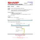
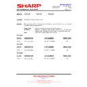
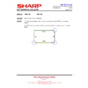
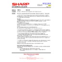
10. C-PWB UNIT
1 ) Disconnect one connector, remove four screws (M3 x 6, Silver), and remove the C-PWB cover.
CAUTION
SCREW TIGHTENING TORQUE
n
0.55 - 0.65N•m
2 ) Disconnect two connectors of the flat cable, remove six screws (M3 x 6 SW+W, Silver), and remove the C-PWB unit.
CAUTION
SCREW TIGHTENING TORQUE
n
0.5 - 0.65N•m
11. 5V POWER SUPPLY UNIT
1 ) Disconnect two connectors, remove four screws (M3 x 6 SW+W, Silver), and remove the 5V power unit.
CAUTION
SCREW TIGHTENING TORQUE
n
0.7 - 0.9N•m
Screw x 4
Connector x 1
Screw x 6
Connector x 2
Screw x 4
Connector x 2
CHAPTER 6. DISASSEMBLY AND ASSEMBLY
PN-L702B DISASSEMBLY AND ASSEMBLY
6 – 13
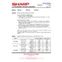
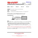
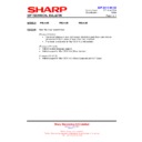
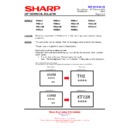
12. AC RELAY UNIT
1 ) Disconnect four connectors, remove four screws (M3 x 6 SW+W, Silver), and remove the AC relay unit.
CAUTION
SCREW TIGHTENING TORQUE
n
0.7 - 0.9N•m
13. INLET HARNESS/AC SWITCH
1 ) Disconnect four connectors, remove one screw A (M4 x 6, Silver), and remove the AC switch. Remove two screws B (M3 x 6 countersunk,
Black), and remove the AC inlet cable.
CAUTION
SCREW TIGHTENING TORQUE
n
Screw A: 0.9 - 1.1N•m
n
Screw B: 0.7 - 0.9N•m
Screw x 4
Connector x 4
Black
White
White
Blue
Confirm that the circle
(o) is on the left side
and it is in the OFF
(o) is on the left side
and it is in the OFF
Screw x 2
AC Inlet Cable
AC Switch
Mark
When attaching, ensure that the
terminals are oriented as
indicated in the engraved mark.
terminals are oriented as
indicated in the engraved mark.
A
Screw
x 1
CHAPTER 6. DISASSEMBLY AND ASSEMBLY
PN-L702B DISASSEMBLY AND ASSEMBLY
6 – 14
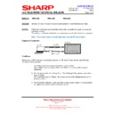
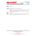
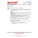
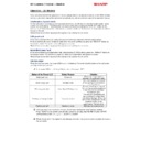
14. SPEAKER L/R
1 ) Remove four screws A (M3 x 6, Silver), remove four screws B ((M3 x 10B, Silver), and remove the speaker cover.
CAUTION
NOTE FOR ASSEMBLY
n
Be careful not to pinch the speaker cable.
SCREW TIGHTENING TORQUE
n
Screw A: 0.7 - 0.9N•m
n
Screw B: 0.55 - 0.65N•m
2 ) Remove two Faston terminals and two screws (M3 x 6 SW+W, Silver), remove two plain washers, and remove the speakers L/R.
CAUTION
NOTE FOR ASSEMBLY
n
The speakers L/R have an engraved mark for identification. Do not install it in the opposite direction.
n
Insert the Faston terminals securely to the bottom to fix firmly.
SCREW TIGHTENING TORQUE
n
0.7 - 0.9N•m
Band
A
Screw
x 4
B
Screw
x 4
Speaker
cover
cover
Speaker cable
When assembling, put the binding band of the
speaker cable inside the cover.
Slightly pull the speaker cable until it is
stopped by the binding band inside the cover.
speaker cable inside the cover.
Slightly pull the speaker cable until it is
stopped by the binding band inside the cover.
L-ch
R-ch
Speaker L
Speaker R
Screw x 2
Washer x 2
Washer x 2
Screw x 2
Washer x 2
Washer x 2
Mark
Mark
Faston terminal
Red
Black
Pull it out while
holding down the
part below.
holding down the
part below.
CHAPTER 6. DISASSEMBLY AND ASSEMBLY
PN-L702B DISASSEMBLY AND ASSEMBLY
6 – 15
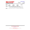
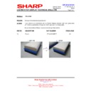
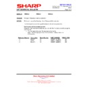
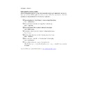
15. LCD MODULE
1 ) Release the wire holder at three positions, release one saddle clamp, release two snap bands, release TKK LWCN-16A at five positions, and
remove the IF tray sheet and the tray angle sheet.
2 ) Remove six screws (M3 x 6, Silver), and remove the IF tray angle R and IF tray L.
CAUTION
SCREW TIGHTENING TORQUE
n
0.7 - 0.9N•m
TKK LWCN-16A×5
Band×2
Tray angle sheet
If tray sheet
Clamp
Holder ×3
Screw x 6
Hook section

