Sharp PN-L601 (serv.man5) Service Manual ▷ View online
CHAPTER 7. DISASSEMBLY AND ASSEMBLY
PN-L601B DISASSEMBLY AND ASSEMBLY
7 – 7
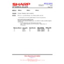
6. SHIELD PLATE ASSY
1 ) Unscrew 15pcs of screw A (M4 x 6 (silver)), 8pcs of screw B (M3 x 6 (silver)) and 2pcs of screw C (3 x 8S/SW (silver)), and remove the Shield
Plate Assy.
CAUTION
NOTE FOR ASSEMBLY
n
Be careful not to get the harness wire caught.
n
Make sure that the locating point of the Shield Plate should NOT be misaligned.
n
Fix the screw B in the sequence of 1 --> 2--> 3.
SCREW TIGHTENING TORQUE
n
screw A, B: 0.9 - 1.1N •m
n
screw C: 0.7 - 0.9N •m
1
3
Bottom
side
side
4
2
Locating points
Locating points
C
Screw
x 2
B
Screw
x 8
A
Screw
x 15
CHAPTER 7. DISASSEMBLY AND ASSEMBLY
PN-L601B DISASSEMBLY AND ASSEMBLY
7 – 8
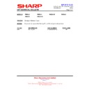
7. I/F PWB
1 ) Disconnect 9 connectors. Unscrew 4pcs of screws (M3 x 8S/SW (silver)), and remove the I/F PWB Assy.
CAUTION
NOTE FOR ASSEMBLY
n
Fix the screw B in the sequence of 1 --> 2--> 3 --> 4.
n
Be careful not to let the boss touch the soldered area of the PWB backside.
SCREW TIGHTENING TORQUE
n
0.7 - 0.9N •m
2 ) Unscrew 6pcs of hexagon screws, 1pc of screw A (M3 x 8B (silver)) and 1pc of screw B (M3 x 6 with a washer (white)). Remove the I/F PWB.
CAUTION
NOTE FOR ASSEMBLY
n
Fix the hexagon screw in the sequence of 1 --> 2--> 3, and then fix the other locations.
SCREW TIGHTENING TORQUE
n
hexagon screw,screw A: 0.55 - 0.65N •m
n
screw B: 0.7 - 0.9N •m
1
2
4
3
Connector x 9
1
2
3
Screw x 6
B
Screw
x 1
B
Screw
x 1
CHAPTER 7. DISASSEMBLY AND ASSEMBLY
PN-L601B DISASSEMBLY AND ASSEMBLY
7 – 9
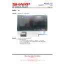
8. MAIN POWER UNIT
1 ) Disconnect 3 connectors and unscrew 9pcs of screws (M3 x 8S/SW (silver)), and remove the Main Power Unit.
CAUTION
NOTE FOR ASSEMBLY
n
Make sure to attach it with the fuse at the upper right.
n
Fix in the sequence of 1 --> 2--> 3--> 4.
SCREW TIGHTENING TORQUE
n
0.7 - 0.9N •m
9. LED POWER UNIT
1 ) Disconnect 6 connectors, unscrew 9pcs of screws (M3 x 8S/SW (silver)), and remove the IDP Power Unit.
CAUTION
NOTE FOR ASSEMBLY
n
Make sure to attach it with the fuse at the upper left.
n
Fix in the sequence of 1 --> 2--> 3--> 4.
SCREW TIGHTENING TORQUE
n
0.7 - 0.9N •m
1
3
2
4
Fuse
Connector x 3
1
3
2
4
Fuse
Connector x 6
CHAPTER 7. DISASSEMBLY AND ASSEMBLY
PN-L601B DISASSEMBLY AND ASSEMBLY
7 – 10
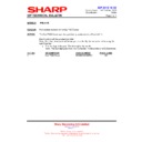
10. RELAY PWB
1 ) Disconnect 6 connectors, unscrew 4pcs of screws (M3 x 8S/SW (silver)), and remove the Relay PWB.
CAUTION
NOTE FOR ASSEMBLY
n
Be careful not to let the boss touch the soldered area of the PWB backside.
n
Fix in the sequence of 1 --> 2--> 3--> 4.
SCREW TIGHTENING TORQUE
n
0.7 - 0.9N •m
11. AC RELAY PWB
1 ) Disconnect 4 connectors, unscrew 6pcs of screws (M3 x 8S/SW (silver)), and remove the AC Relay PWB.
CAUTION
NOTE FOR ASSEMBLY
n
Be careful not to let the boss touch the soldered area of the PWB backside.
n
Fix in the sequence of 1 --> 2--> 3--> 4--> 5--> 6.
1
3
2
4
Connector x 6
4
2
6
3
1
5
Connector x 4

