Sharp PN-K321 (serv.man3) Service Manual ▷ View online
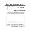
SERVICE MANUAL
CODE: 00ZPNK321SM2E
LCD MONITOR
MODEL PN-K321/K321H/K322B/K322BH
* The second generation model with the significantly improved LCD module and the PWB is shipped
from January, 2014 sequentially. There are some incompatible parts between the original model and the
CHAPTER 1. OUTLINE OF THE PRODUCT ······················································· 1-1
CHAPTER 2. INSTALLATION, ADJUSTMENT, SETTING ································· 2-1
CHAPTER 3. INPORTANT INFORMATION FOR SERVICING THE DISPLAY ··· 3-1
CHAPTER 4. SERVICE MENU/VARIOUS SETTING TOOL OPERATING PROCEDURES ······· 4-1
CHAPTER 5. FIRMWARE UPDATE PROCEDURES ·········································· 5-1
CHAPTER 6. DISASSEMBLY AND ASSEMBLY ··············································· 6-1
CHAPTER 7. TOROUBLESHOOTING ································································ 7-1
CHAPTER 8. HARDWARE DESCRIPTIONS ······················································ 8-1
CHAPTER 9. CHANGES FROM ORIGINAL MODEL OF PN-K321 ···················· 9-1
SHARP CORPORATION
CONTENT
Parts marked with “
!”
are important for maintaining the safety of the set. Be sure to replace these
parts with specified ones for maintaining the safety and performance of the set.
:’14/Jan

