Sharp LL-T2020 (serv.man7) Service Manual ▷ View online
LL-T2020
TROUBLESHOOTING
4 – 1
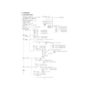
CHAPTER 4. TROUBLESHOOTING
(Yes)
(Yes)
(Yes)
(Yes)
(Yes)
(Yes)
Green LED comes on when the power button is
pressed?
pressed?
The screen is displayed properly in each video
mode?
mode?
AC cable is connected to the power supply
unit?
unit?
Input signal port is the one to which analog
signal cable is connected?
signal cable is connected?
Test terminals LD401, LD402, and LD403 are
DC+3.3V?
DC+3.3V?
Test terminal LD623 changes its level when
POWER switch is turned on and off?
POWER switch is turned on and off?
Press INPUT key to switch over to the
correct input signal port.
correct input signal port.
Check DC+5V power supply line (DV5A)
and POWER_CTL1 signal and circuits
around Q807.
and POWER_CTL1 signal and circuits
around Q807.
Check the connection line of LD623, and
check the CN601, SW PWB and cable.
check the CN601, SW PWB and cable.
Remove the analog signal cable. After a short
while time, the LED color changes form green
to orange.
while time, the LED color changes form green
to orange.
(Yes)
(Yes)
(No)
(No)
(Yes)
(Yes)
(No)
(No)
(No)
(No)
(Yes)
(Yes)
(No)
(No)
(No)
(No)
(No)
(Yes)
(No)
(Yes)
(Yes)
(No)
(No)
(No)
Perform 1
B/L is lit?
No error.
Check AC cable connection.
Check power supply unit switch.
Check circuits around IC601.
Check circuits around IC801.
Check circuits around IC401.
Check RESET circuit around IC602.
Check IC602 and clock circuit around X601.
Check SW101 and circuits around IC101.
The power supply unit is switched on?
SW101 is on 1st pin side?
Test terminal LD811 is DC+5V?
Test terminal LD815 is DC+5V?
4th pin of IC602 is in H level (DC+5 V)?
C610-side terminal signal of X601 is normal?
Test terminal LD608 is DC+3.3V?
1
Perform 2
Perform 3
Perform 4
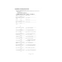
Check whether the following cables are connected correctly.
In addition, check whether the PCs video mode is properly set to the signal timing which meets this machine.
In addition, check whether the PCs video mode is properly set to the signal timing which meets this machine.
Attached cables
Dedicated AC adapter
Dedicated analog signal cable (DVI-A cable)
Dedicated digital signal cable (DVI-D cable)
Dedicated AC adapter
Dedicated analog signal cable (DVI-A cable)
Dedicated digital signal cable (DVI-D cable)
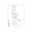
The display does not work. (with analog connection, DVI-A cable use)
LL-T2020
TROUBLESHOOTING
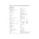
4 – 2
(No)
(No)
(No)
(No)
(No)
(Yes)
(Yes)
(Yes)
(No)
(Yes)
(Yes)
(No)
(Yes)
(Yes)
(No)
(Yes)
(No)
(Yes)
(No)
(Yes)
(No)
(Yes)
(Yes)
(Yes)
(Yes)
(No)
(No)
The port from which the analog signal cable
was removed is the input signal port selected?
was removed is the input signal port selected?
48th pin and 49th pins of IC602 are in H level
(DC+3.3V)?
(DC+3.3V)?
LD613 and LD616 are in H level (about
DC+1.9V)?
DC+1.9V)?
LD808 is less than DC+1.0V at maximum
brightness?
brightness?
1st pin of CN2, CN3, CN4, CN5, CN6, and CN7
on inverter PWB unit is about 790 Vrms? (Use
caution not to get electric shock accident. Use
a high-voltage probe (more than 100:1) for
measuring voltage.)
on inverter PWB unit is about 790 Vrms? (Use
caution not to get electric shock accident. Use
a high-voltage probe (more than 100:1) for
measuring voltage.)
Check analog signal cable and CN101
(CN201).
(CN201).
Check SDA and SCL signals and circuits
around IC402 and IC602.
around IC402 and IC602.
Press INPUT key to switch over to the
correct input signal port.
correct input signal port.
When CN802 cable is removed, check the
LD801 is DC+12V.
LD801 is DC+12V.
Check inverter unit, inverter cable and their
connections.
connections.
Check the power unit and cable and their
connections, and DC+12V power supply
line.
connections, and DC+12V power supply
line.
Check BL_EN signal and circuits around
CN802.
CN802.
Check BRT_VR signal and circuits around
IC604.
IC604.
Signal waveforms of test terminals LD304,
LD305 (LD317, LD318) are normal?
LD305 (LD317, LD318) are normal?
Signal waveforms of test terminals LD312,
LD323 (LD313, LD324) are normal?
LD323 (LD313, LD324) are normal?
Signal waveforms of 31st and 32nd pins of
IC402 are normal?
IC402 are normal?
Check SW PWB and SW cable and their
connections.
connections.
48th pin of IC602 is in H level (DC+3.3V)?
continued from 1
LD613 is H in level (about DC+1.9V)?
Check SW PWB and SW cable and their
connections.
connections.
Test terminal LD801 is DC+12V?
LD807 is in H level (DC+5V)?
Check lamp inside LCD module.
Check circuits around IC602.
Check Q601 and its surrounding circuits.
Replace inverter PWB unit with a new one.
Check circuits around IC602.
Check Q601 and its surrounding circuit.
Check circuits around IC301 and IC302.
2
3
LL-T2020
TROUBLESHOOTING
4 – 3
(No)
(No)
(No)
(Yes)
(Yes)
(No)
(Yes)
(No)
(Yes)
(No)
(Yes)
(No)
(Yes)
(No)
(Yes)
(Yes)
(Yes)
(No)
(No)
(No)
(Yes)
(Yes)
(Yes)
(Yes)
(No)
(Yes)
(No)
(No)
(No)
(Yes)
(No)
(No)
(Yes)
(No)
(Yes)
(Yes)
Check DC+5V power supply line (PV5) ,
POWER_CTL3 signal, and circuits around
Q807.
POWER_CTL3 signal, and circuits around
Q807.
Check DC+2.5V power supply line (DV25),
POWER_CTL4 signal, and circuits around
IC802.
POWER_CTL4 signal, and circuits around
IC802.
Check DC+12V power supply line (LCDV),
POWER_CTL2 signal, and circuits around
Q803.
POWER_CTL2 signal, and circuits around
Q803.
Check clock circuit around IC501 and X501.
Clock (R508) and DE (R502) signal outputs
are normal?
are normal?
ADJUSTMENT and MODE SELECT are set
properly?
properly?
Signal waveform of test terminal LD502 is
normal?
normal?
ADJUSTMENT and MODE SELECT are set
properly?
properly?
Adjust according to "screen adjustment
procedure".
procedure".
Adjust according to "screen adjustment
procedure".
procedure".
Check circuits around IC301, IC302, and
IC402.
IC402.
Check circuits around IC701, and CN701
and LCD module.
and LCD module.
Check DC+5V power supply line (DV5A),
POWER_CTL1 signal, and circuits around
Q807.
POWER_CTL1 signal, and circuits around
Q807.
Test terminals LD405, LD523, and LD701 are
DC+3.3V?
DC+3.3V?
Signal waveform of test terminal LD565 is
normal?
normal?
Test terminals LD401, LD402, and LD403 are
DC+3.3V?
DC+3.3V?
Test terminal LD815 is DC+5V?
Test terminal LD806 is DC+5V?
Test terminal LD801 is DC+12V?
Test terminal LD501 is DC+2.5V?
LD816 is DC+12.0V?
36th pin of LC602 is in H level (DC+5V)?
The entire LCD screen is white?
The entire LCD is black?
The size of LCD screen is abnormal?
LCD screen jitters or flickers?
Check circuits around IC401.
Check circuits around IC403.
Check circuits around IC601.
Test terminal of LD701 is DC+12V?
Check circuits around X601 and IC602.
Check circuits around IC502.
Check circuits around CN701.
Check PLL circuits around IC402.
Check circuits around IC502.
4
Check inverter unit, inverter cable and their
connections.
connections.
(No)
(Yes)
When CN802 cable is removed, LD801 is
DC+12V?
DC+12V?
Check the power unit and cable and their
connections, and DC+12V power supply
line.
connections, and DC+12V power supply
line.
LL-T2020
TROUBLESHOOTING
4 – 4
(No)
(No)
(No)
(Yes)
(Yes)
(Yes)
(Yes)
(No)
(No)
(Yes)
(No)
(No)
(Yes)
(Yes)
(Yes)
(No)
(Yes)
(No)
(No)
(Yes)
(No)
(Yes)
(No)
(Yes)
(No)
(Yes)
(Yes)
(No)
(Yes)
(Yes)
(No)
(No)
(Yes)
(Yes)
GAIN CONTROL and WHITE BALANCE
are set properly?
are set properly?
Analog color signal output (C302, C303,
C305, C319, C320, and C322) is normal?
C305, C319, C320, and C322) is normal?
Digital color signal output of IC402 (ID0
ID47) is normal?
ID47) is normal?
Digital color signal output of IC502 (OD0
OD47) is normal?
OD47) is normal?
Check circuits around IC701, and CN701
and LCD module.
and LCD module.
Check circuits around IC402, IC404, and
IC602.
IC602.
Digital color signal output of IC402 (ID0
ID47) is normal?
ID47) is normal?
Press INPUT key to switch over to the
correct input signal port.
correct input signal port.
Check CN101 and 201, and signal source
and digital signal cable.
and digital signal cable.
Check circuits around IC101, IC103 and
IC201.
IC201.
Check CN101 and 201, and signal source
and digital signal cable.
and digital signal cable.
Display is normal in composite sync and sync-
on-green signal input.
on-green signal input.
AUTO function of GAIN CONTROL operates
properly?
properly?
Input signal port is the one to which digital
signal cable is connected?
signal cable is connected?
Waveforms of IC103s and 201s 1st and 2nd
pins change normally when resolution is
changed?
pins change normally when resolution is
changed?
Test terminals LD110, LD111, LD112, LD113,
LD210, LD211, LD212, LD213 are DC+3.3V?
LD210, LD211, LD212, LD213 are DC+3.3V?
CN101 and 201 signals (at 1st, 2nd, 9th, 10th,
17th, 18th, 23rd, and 24th pins) are normal?
17th, 18th, 23rd, and 24th pins) are normal?
IC102 and IC202 signal output (ID0 ID47,
HIS, IVS, ICK, IACT) are normal?
HIS, IVS, ICK, IACT) are normal?
LCD screen color is abnormal?
Input is changed over properly?
No error.
Display is normal in analog input?
LD101 and LD201 are in H level (DC+5V)?
Check circuits around IC502.
Adjust according to "screen adjustment
procedure".
procedure".
Check circuits around IC402.
Check circuits around IC402 and IC502.
Check circuits around IC502 and IC701.
Check circuits around IC402 and IC404.
Check circuits around IC602.
check circuits around IC602 and IC605.
Check circuits around IC402.
First, check with analog signal input.
Check circuits around IC104 and IC203.
Check circuits around IC102 and IC202.
continued from 4
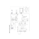
The display does not work. (with digital connection, DVI-D cable use)
Display

