Sharp LL-T15G1 (serv.man6) Service Manual ▷ View online
LL-T15G1/E15G1
CONNECTOR SIGNAL NAME • BLOCK DIAGRAM • CIRCUIT DIAGRAM • PWB LAYOUT
5 – 1
CHAPTER 5. CONNECTOR SIGNAL NAME • BLOCK DIAGRAM •
CIRCUIT DIAGRAM • PWB LAYOUT
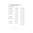
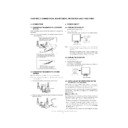
1. CONNECTOR SIGNAL NAME
CONNECTOR W01
CONNECTOR W07
CONNECTOR W06
1
Red
1
GND
1
GND
2
Green
2
BO7
2
DCLK
3
Blue 3
BO6
3
GND
4
Ground
4
BO5
4
DE-O
5
Ground
5
BO4
5
VSYNC
6
R-GND
6
GND
6
HSYNC
7
G-GND
7
BO3
7
N.C
8
B-GND
8
BO2
8
GND
9
+5V
9
BO1
9
BE7
10
Ground
10
BO0
10
BE6
11
N.C
11
GND
11
BE5
12
(SDA)
12
GO7
12
BE4
13
H-sync 13
GO6
13
GND
14
V-sync
14
GO5
14
BE3
15
(SCL)
15
GO4
15
BE2
16
GND
16
BE1
17
GO3
17
BE0
18
GO2
18
GND
19
GO1
19
GE7
CONNECTOR W04
20
GO0
20
GE6
1
POW1
21
GND
21
GE5
2
GND
22
RO7
22
GE4
3
LED1
23
RO6
23
GND
4
LED2
24
RO5
24
GE3
5
SN1
25
RO4
25
GE2
6
SN2
26
GND
26
GE1
27
RO3
27
GE0
28
RO2
28
GND
29
RO1
29
RE7
30
RO0
30
RE6
CONNECTOR W05
31
GND
31
RE5
1
N.C
32
GND
32
RE4
2
CON
33
N.C
33
GND
3
VEE
34
N.C
34
RE3
4
GND
35
N.C
35
RE2
5
VDD
36
GND
36
RE1
37
RE0
38
VLCD
39
VLCD
40
GND
LL-T15G1/E15G1
CONNECTOR SIGNAL NAME • BLOCK DIAGRAM • CIRCUIT DIAGRAM • PWB LAYOUT
5 – 2
2. BLOCK DIAGRAM
MAIN BOARD(TFT LCD DISPLAY ANALOG INTERFACE CONTROL BOARD)
IC01 AD9883
R
G
B
H
V
SCL
SDA
IIC
Camp
Video gain
Video level
Sync processor
and clock
generator input
Sync-processor
and clock
generator
generator
R
G
B
8
8
8
ADC
Power
management
DATACLK
HSOUT
VSOUT
SOGOUT
VCLK1
FCLK1
IC03
TLC2933
IC
05
MTV230
IC04
EEPROM
ISCL
ISDA
DC 12Vin
POWER
Control
+5V
+3.3V
HSOUT
VSOUT
OSD-R
OSD-G
OSD-B
IC07
OSD
TFT
LCD
EEPROM
Interface
Control
Register
Input mode
Detection &
Calibration
Control
Center
Output
Sync-processor
and clock
generator
generator
Digital
Data
Processor
Scaling
Dithering
IC02
AM101A-2
LL-T15G1/E15G1
CONNECTOR SIGNAL NAME • BLOCK DIAGRAM • CIRCUIT DIAGRAM • PWB LAYOUT
5 – 3
A
B
C
D
8
7
6
5
4
3
2
1
1
2
3
4
5
6
7
8
D
C
B
A
3. CIRCUIT
DIAGRAM
LL-T15G1/E15G1
CONNECTOR SIGNAL NAME • BLOCK DIAGRAM • CIRCUIT DIAGRAM • PWB LAYOUT
5 – 4
4.
P
W
B
LA
YO
UT
A SI
DE
Display

