Sharp LL-T15A1 (serv.man9) Service Manual ▷ View online
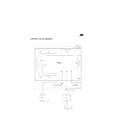
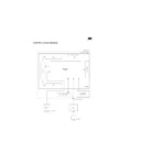
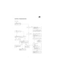
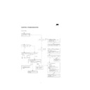
CHAPTER 4. BLOCK DIAGRAM
LAMP
SORCE DRIVER
DISPLAY UNIT
LCD MODULE UNIT
GATE DR
IVER
INTERFACE
UNIT
INVERTER
LAMP
LCD PANEL
KEY-SWITCH UNIT
BRIGHTNESS
SENSOR UNIT
DC CONNECTOR
RGA,H/V
INPUT
[FROM PC]
AC
ADAPTER
[AC INPUT]
POWER INPUT CONNECTOR
Connector: S6B-PH-SM3-TB (JST)
Pin No.
Symbol
Description
1
NC
2
NC
3
GND
Ground
4
GND
Ground
5
12V
+12Vdc
6
12V
+12Vdc
ANALOG RGB INPUT CONNECTOR
Connector: S12B-PH-SM3-TB (JST)
Pin No.
Symbol
Description
1
GND
Ground
2
R
Analog Red
3
GND
Ground
4
G
Analog Green
5
GND
Ground
6
B
Analog Blue
7
GND
Ground
8
HSY
Horizontal Sync
9
VSY
Vertical Sync
10
5V
+5Vdc
11
SDL
DDC Serial Data
12
SCL
DDC Data Clock
BRIGHTNESS CONTROL CONNECTOR
Connector : S2B-PH-SM3-TB (JST)
Pin No.
Symbol
Description
1
Signal input
Sensor Signal Input
2
5V
+5Vdc
CONTROL KEY CONNECTOR
Connector: S8B-PH-SM3-TB (JST)
Pin No.
Symbol
Description
1
POWER SW
ON/OFF
2
GND
Ground
3
LED2
LED control signal
4
LED1
+5V
5
SW4
6
SW3
UP
7
SW2
DOWN
8
SW1
+
BACKLIGHT POWER CONNECTOR
Connector: S5B-PH-SM3-TB (JST)
Pin No.
Symbol
Description
1
CBKLT
0/3.3Vdc (High Active)
2
NC
3
CBTNS
0.0 ~ 3.5Vdc
4
GND
Ground
5
12V
+12Vdc Input
Display

