Sharp LL-T1501A (serv.man12) Service Manual ▷ View online
■
The connector pin
Number
Function
1
Red video signal input
2
Green video signal input
3
Blue video signal input
4
N.C.
5
N.C.
6
For red video signal GND
7
For green video signal GND
8
For blue video signal GND
9
DDC + 5V
10
N.C.
11
GND
12
DDC data
13
For H-sync signal input
14
For V-sync signal input
15
DDC clock
■
Power management
The monitor is based on VESA DPMS (Display Power Management
Signaling).
Signaling).
To activate the monitor’s Power Management function, both the video
card and the computer must conform to the VESA DPMS standard.
card and the computer must conform to the VESA DPMS standard.
DPMS mode
Screen
Power
consumption
H-sync
V-sync
ON
Display on
23W
Yes
Yes
STANDBY
Display off
3W
No
Yes
SUSPEND
Yes
No
OFF
No
No
■
DDC (Plug & Play)
This monitor supports the VESA DDC (Display Data Channel) stand-
ard.
ard.
DDC is a signal standard for carrying out Plug & Play functions on the
monitor or PC. It transfers information such as degree of resolution
between the monitor and PC. You can use this function if your PC is
DDC compliant and if it is set so that it can detect the Plug & Play
monitor.
monitor or PC. It transfers information such as degree of resolution
between the monitor and PC. You can use this function if your PC is
DDC compliant and if it is set so that it can detect the Plug & Play
monitor.
There are many varieties of DDC due to the differences between
systems. This monitor works with DDC1 and DDC2B.
systems. This monitor works with DDC1 and DDC2B.
2. PRODUCT DESCRIPTION
■
Front view
1. Power button
Pressing this button turns the power on when the main power
switch is on. (After turning the power on, it may take a little time
before the screen displays.) Press the button again to turn the
power off.
switch is on. (After turning the power on, it may take a little time
before the screen displays.) Press the button again to turn the
power off.
2. Power LED
This LED is lit green when in use and orange when in power-sav-
ing mode.
ing mode.
3.
buttons
When the On Screen Display (OSD) Menu is displayed:
These buttons are used to increase or decrease the value of a
selected option.
When the OSD Menu is not displayed:
These buttons are used to adjust backlight brightness.
These buttons are used to increase or decrease the value of a
selected option.
When the OSD Menu is not displayed:
These buttons are used to adjust backlight brightness.
4. SELECT button
Selects the menu option to be adjusted.
5. MENU button
This button is used to pop-up, select and close the OSD Menu.
6. BRIGHT button
This button is used to change the backlight to any of three levels
of brightness.
On [AUTO] setting the brightness sensor will automatically adjust
to the right brightness.
of brightness.
On [AUTO] setting the brightness sensor will automatically adjust
to the right brightness.
7. Brightness sensor
Measures the brightness of the surrounding environment.
5
4
3
2
1
15
14
13
12
11
10
9
8
7
6
(Mini D-sub connector with 15 pins)
5
4
3
2 1
7
6
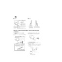
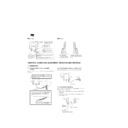
Lightly holding both sides of the monitor,
adjust it to a suitable viewing angle.
adjust it to a suitable viewing angle.
Note: When adjusting the angle, be
sure to hold the green section only.
Pressure from hands on the LCD panel
could cause damage.
sure to hold the green section only.
Pressure from hands on the LCD panel
could cause damage.
Adjusting the angle of the monitor
■
Rear View
■
Side view
CHAPTER 2. CONNECTION, ADJUSTMENT, OPERATION AND FUNCTIONS
1. CONNECTION
1-1. Connecting the monitor to a computer
(PC etc.)
When connecting, ensure that both the monitor and computer are
switched off.
switched off.
1-2. Connecting the monitor to a power source
Before connecting, first turn off the monitor’s main power switch.
1-3. Connecting a USB device
If your computer or computer’s OS is USB compatible, the monitor
can be connected to a USB device.
can be connected to a USB device.
1. Plug one end of the USB cable (provided) into the monitor’s USB
upstream port.
2. Connect the other end of the USB cable into the computer or the
USB downstream port.
USB port: Upstream (1 Port)
A USB-ready computer or
self-powered USB hub can
be connected here.
A USB-ready computer or
self-powered USB hub can
be connected here.
Security lock anchor
By connecting a security lock (purchased separately) to the
security lock anchor, the monitor is fixed so that it cannot
be transported.
By connecting a security lock (purchased separately) to the
security lock anchor, the monitor is fixed so that it cannot
be transported.
The theft prevention hole works in conjunction with
Kensington Micro Saver Security Systems.
Kensington Micro Saver Security Systems.
RGB signal cable
This is to be connected to the
computer's analog RGB output
terminal.
This is to be connected to the
computer's analog RGB output
terminal.
Power connector
The power cord is
connected here.
The power cord is
connected here.
Ventilation
openings
openings
Note: Never block the ventilation
openings as this may lead to
overheating inside the monitor
and result in malfunction
openings as this may lead to
overheating inside the monitor
and result in malfunction
Main power switch
( I ) Turns the monitor on.
(O) Turns the monitor off.
( I ) Turns the monitor on.
(O) Turns the monitor off.
USB port: Downstream (2 ports)
A USB device can be connected
here.
A USB device can be connected
here.
Firmly insert the analog RGB output terminal
(mini D-sub 15 pin with 3 rows) then tighten the
screws each side.
(mini D-sub 15 pin with 3 rows) then tighten the
screws each side.
RGB cable
If connecting to a D-sub 15 pin 2 row Apple Power
Macintosh, attach a Macintosh conversion adapter
(to be purchased separately) to the RGB signal
cable.
Macintosh, attach a Macintosh conversion adapter
(to be purchased separately) to the RGB signal
cable.
Macintosh conversion adapter
RGB signal cable
After connecting the adapter, tighten the
screws on each side to fix into place.
After connecting the adapter, tighten the
screws on each side to fix into place.
1
2
AC outlet
Power cord
USB cable
(provided)
(provided)
USB upstream port
To the computer or another
USB hub’s downstream port
USB hub’s downstream port
3. Plug the USB device into the monitor’s USB downstream port.
Notes:
•
Before connecting, ensure that the shape of the USB cable
connector is correct.
connector is correct.
•
For information regarding the USB function (such as set-up)
please refer to the operation manual of the computer to be
connected.
please refer to the operation manual of the computer to be
connected.
•
Some computers, OS and other devices may not be able to be
activated. To ascertain a certain device’s USB compatibility,
please contact the manufacturer of the device.
activated. To ascertain a certain device’s USB compatibility,
please contact the manufacturer of the device.
USB specifications
Standard: Based on USB standard (Rev. 1.1), bus-powered hub
Downstream port power supply: 100 mA per port maximum
Downstream port power supply: 100 mA per port maximum
2. POWER ON/OFF
2-1. Turning the power on
1. Turn on the monitor’s main switch.
2. Turn on the computer.
3. Press the monitor’s power button. The power LED will be lit green,
and the screen will display an image.
Note: When setting up this monitor for the first time or after having
changed an aspect of the current system, perform an automat-
ic screen adjustment before use.
ic screen adjustment before use.
Installing set-up information
Depending on the computer or OS, it may be necessary to use the
computer to operate the installation of monitor set-up information etc.
If so, follow the steps below to install the monitor set-up information.
computer to operate the installation of monitor set-up information etc.
If so, follow the steps below to install the monitor set-up information.
Notes:
•
Depending on the computer type, command names and meth-
ods may differ. Please follow the computer’s own operation
manual while reading this.
ods may differ. Please follow the computer’s own operation
manual while reading this.
•
This explanation assumes that the floppy disk drive is "A drive".
If the floppy disk drive of your computer is not "A drive", please
read the below substituting the floppy disk drive you are using
in place of "A drive" or "A ".
If the floppy disk drive of your computer is not "A drive", please
read the below substituting the floppy disk drive you are using
in place of "A drive" or "A ".
[ For Windows95 ]
Installing monitor set-up information into Windows95.
This explanation assumes that the floppy disk drive is "A drive".
This explanation assumes that the floppy disk drive is "A drive".
1.
Place the Monitor Settings Adjustment Disk (provided) into the
computer’s A drive.
computer’s A drive.
2.
Click on the [Start] button. From [Settings], choose [Control
Panel].
Panel].
3.
Double click on [Display].
4.
Click on [Settings], [Advanced Properties], and [Monitor], then
[Change].
[Change].
5.
Click on [Have Disk], confirm that [Copy manufacturer’s files
from:] is [A:] then click [OK].
from:] is [A:] then click [OK].
6.
Confirm that the monitor details are selected, and click [OK].
7.
Check that the monitor details are displayed, then click [Apply].
8.
Click [OK], and close the window.
9.
Remove the Monitor Settings Adjustment Disk from the A drive.
[ For Windows98 ]
Installing monitor set-up information into Windows98.
If the "Add New Hardware Wizard" has appeared:
(This explanation assumes that the floppy disk drive is "A drive")
If the "Add New Hardware Wizard" has appeared:
(This explanation assumes that the floppy disk drive is "A drive")
1.
Place the Monitor Settings Adjustment Disk (provided) into the
computer’s A drive.
computer’s A drive.
2.
Click [Next].
3.
Check [Display a list of all the drivers in a specific location, so
you can select the driver you want.], then click [Next].
you can select the driver you want.], then click [Next].
4.
When [Models] is displayed, click on [Have Disk], confirm that
[Copy manufacturer’s files from:] is [A:], and click [OK].
[Copy manufacturer’s files from:] is [A:], and click [OK].
5.
Confirm that the monitor details are selected, then click [Next],
[Next], and [Finish]. If the "Add New Hardware Wizard" appears,
repeat the installation commands beginning from 2 above.
[Next], and [Finish]. If the "Add New Hardware Wizard" appears,
repeat the installation commands beginning from 2 above.
6.
Remove the Monitor Settings Adjustment Disk from the A drive.
If the "Add New Hardware Wizard" has not appeared:
(This explanation assumes that the floppy disk drive is "A drive")
(This explanation assumes that the floppy disk drive is "A drive")
1.
Place the Monitor Settings Adjustment Disk in the computer’s A
drive.
drive.
2.
Click on the [Start] button. From [Settings], choose [Control
Panel].
Panel].
3.
Double click on [Display].
4.
Click on [Settings], [Advanced] and [Monitor].
5.
In [Options], check [Automatically detect Plug & Play monitors]
and click on [Change].
and click on [Change].
6.
Click [Next].
7.
Click on [Display a list of all the drivers in a specific location, so
USB downstream port
Main power switch
Power LED
Power button
you can select the driver you want.], then click [Next].
8.
When [Models] is displayed, click on [Have Disk], confirm that
[Copy manufacturer’s files from:] is [A:], and click [OK].
[Copy manufacturer’s files from:] is [A:], and click [OK].
9.
Confirm that the monitor details are selected, then click [Next],
[Next], and [Finish].
[Next], and [Finish].
10. Check that the monitor details are displayed, then click [Apply].
11. Click [OK], and close the window.
12. Remove the Monitor Settings Adjustment Disk from the A drive.
[For Windows2000]
Installing monitor set-up information into Windows2000.
This explanation assumes that the floppy disk drive is "A drive".
This explanation assumes that the floppy disk drive is "A drive".
1.
Place the Monitor Settings Adjustment Disk (provided) into the
computer’s A drive.
computer’s A drive.
2.
Click on the [Start] button. From [Settings], choose [Control
Panel].
Panel].
3.
Double click on [Display].
4.
Click on [Settings], [Advanced] and [Monitor].
5.
Click on [Properties], [Driver] and [Update Driver].
6.
When [Upgrade Device Driver Wizard] appears, click [Next].
7.
Check [Display a list of the known drivers for this device so that I
can choose a specific driver] and click [Next].
can choose a specific driver] and click [Next].
8.
When [Models] is displayed, click on [Have Disk], confirm that
[Copy manufacturer’s files from:] is [A:], and click [OK].
[Copy manufacturer’s files from:] is [A:], and click [OK].
9.
Select the monitor from the list displayed and click [Next].
10. Click [Next], confirm that the monitor’s name appears on the
screen, and click [Finish]. If [Digital Signature Not Found] ap-
pears, click [Yes].
pears, click [Yes].
11. Click on [Close].
12. Click [OK], and close the window.
13. Remove the Monitor Settings Adjustment Disk from the A drive.
[For WindowsMe]
Installing monitor set-up information into WindowsMe.
If the "Add New Hardware Wizard" has appeared:
(This explanation assumes that the floppy disk drive is "A drive")
(This explanation assumes that the floppy disk drive is "A drive")
1.
Place the Monitor Settings Adjustment Disk (provided) into the
computer’s A drive.
computer’s A drive.
2.
Check [Specify the location of the driver [Advanced]] and click
[Next].
[Next].
3.
Check [Display a list of all the drivers in a specific location, so
you can select the driver you want.], then click [Next].
you can select the driver you want.], then click [Next].
4.
When [Models] is displayed, click on [Have Disk], confirm that
[Copy manufacturer’s files from:] is [A:], and click [OK].
[Copy manufacturer’s files from:] is [A:], and click [OK].
5.
Select the monitor details from the list, then click [Next], [Next],
and [Finish]. If the "Add New Hardware Wizard" appears, repeat
the installation commands beginning from 2 above.
and [Finish]. If the "Add New Hardware Wizard" appears, repeat
the installation commands beginning from 2 above.
6.
Remove the Monitor Settings Adjustment Disk from the A drive.
If the "Add New Hardware Wizard" has not appeared:
(This explanation assumes that the floppy disk drive is "A drive")
(This explanation assumes that the floppy disk drive is "A drive")
1.
Place the Monitor Settings Adjustment Disk in the computer’s A
drive.
drive.
2.
Click on the [Start] button. From [Settings], choose [Control
Panel].
Panel].
3.
Double click on [Display].
4.
Click on [Settings], [Advanced] and [Monitor].
5.
In [Options], check [Automatically detect Plug & Play monitors]
and click on [Change].
and click on [Change].
6.
Check [Specify the location of the driver [Advanced]] and click
[Next].
[Next].
7.
Check [Display a list of all the drivers in a specific location, so
you can select the driver you want.] and click [Next].
you can select the driver you want.] and click [Next].
8.
When [Models] is displayed, click on [Have Disk], confirm that
[Copy manufacturer’s files from:] is [A:], and click [OK].
[Copy manufacturer’s files from:] is [A:], and click [OK].
9.
Select the monitor details, then click [Next], [Next], and [Finish].
10. Check that the monitor details are displayed, then click [Apply].
11. Click [OK], and close the window.
12. Remove the Monitor Settings Adjustment Disk from the A drive.
2-2. Turning the power off
1.
Turn the computer off.
2.
Press the monitor’s power button.
The Power LED will disappear.
3.
Turn the monitor off at the main switch.
3. ADJUSTING THE SCREEN DISPLAY
If necessary, the screen can be adjusted as follows.
[Automatic screen adjustment (right column)]
The clock, phase, H-POS (horizontal positioning) and V-POS (vertical
positioning) functions can be adjusted automatically.
positioning) functions can be adjusted automatically.
[Adjustment of backlight]
Brightness of backlight can be adjusted.
[Manual adjustment]
Fine adjustments can be made using the On Screen Display (OSD)
Menu.
Menu.
Note: All adjustments will be saved even after turning the power off.
All Reset MENU
All adjustment values can be returned to their original ex-factory val-
ues in one command.
ues in one command.
1.
Press the power button to turn off the monitor power.
2.
Press the MENU button and the SELECT button simultaneously,
and while doing this press the power button (i.e. turn the power
on). When [ALL RESET] appears on the screen, the reset is
complete.
and while doing this press the power button (i.e. turn the power
on). When [ALL RESET] appears on the screen, the reset is
complete.
Notes:
•
While ALL RESET is displayed, the control buttons do not func-
tion.
tion.
•
It is not possible to reset values when the adjustment lock is in
place. Remove the adjustment lock before attempting to oper-
ate control buttons.
place. Remove the adjustment lock before attempting to oper-
ate control buttons.
Adjustment lock function
By disabling the control buttons (i.e. setting the lock) any attempted
changes to adjusted values will be voided.
changes to adjusted values will be voided.
1.
Press the power button to turn off the monitor power.
2.
While pressing the MENU button, press the power button (i.e.
turn the power on).
When the menu is unlocked:
turn the power on).
When the menu is unlocked:

