Sharp LL-T1500A (serv.man13) Service Manual ▷ View online
CHAPTER 2. REPLACING LAMPS (Removing LCD module)
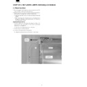
[1] Replacing lamps
·
After removing the LCD module from the unit according to 2. Re-
moving the LCD module, replace the lamp units.
moving the LCD module, replace the lamp units.
·
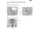
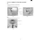
Replace the lamp units using the following replacement procedure,
referring to Fig.1 (enlarged view) and Fig. 2 (overall view).
referring to Fig.1 (enlarged view) and Fig. 2 (overall view).
·
There are two lamp units at the top and bottom of the LCD
module.
module.
·
Wear finger sacks when doing this work, not to contaminate or
damage the LCD panel. Use caution prevent the entrance of
dirt or dust into the module.
damage the LCD panel. Use caution prevent the entrance of
dirt or dust into the module.
[Replacement procedure]
Turn the module over and remove the screws A in Figs. 1. (1
screw for each unit). Put a finger on the concave B and remove
the lamp unit in a straight line.
screw for each unit). Put a finger on the concave B and remove
the lamp unit in a straight line.
·
Use caution not to apply undue force on the lamp.
Replace the lamp unit with a new one.
Reinstall in the reverse order of disassembly.
·
Tighten the screw and make sure the lamp unit won’t move.
B
Drawing
direction
direction
Screw A
Fluorescent
lamp lead wire
lamp lead wire
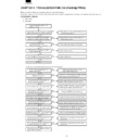
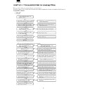
[2] Removing LCD module
Procedure
Disassembly
1. Remove the 2 screws in
and remove the display mask (front
cabinet).
·
A connector
is removed so that stress may not be applied to
the control circuit board cable when a front cabinet is removed.
·
Use caution not to break the latches in
when removing the
front cabinet.
2. Remove the 8 screws in
and remove the module.
·
Use caution not to drop the LCD module.
3. Remove the 2 screws in
and remove the LCD cable connector
from the module.
Reassembly
Reassemble the LCD module using the steps from 1 to 3 in re-
verse.
verse.
·
Use caution not to get the cables caught in the cabinet when
reassembling.
reassembling.
1
Front cabinet
2
3
4
5
CHAPTER 3. CONNECTION, ADJUSTMENT, OPERATION AND FUNCTIONS
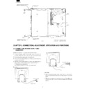
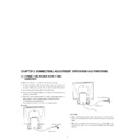
[1] CONNECTING POWER SUPPLY AND
COMPUTER
·
Make sure both the LCD monitor and computer are OFF.
Connect the signal cable to the analog output terminal of the
computer. Make sure to tighten the connector screws of the cable.
computer. Make sure to tighten the connector screws of the cable.
Connect the power supply cable to the wall outlet.
Turn on the main power switch of the monitor and then turn on the
computer power switch.
computer power switch.
When the monitor power switch is turned on, the green power-on
lamp comes on and the screen appears. Adjust the screen
lamp comes on and the screen appears. Adjust the screen
Automatic screen adjustment
After using the monitor, turn off the main power switch.
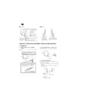
Rear view
[CAUTION]
·
When removing the power cable, make sure that both the com-
puter and the monitor are OFF and hold the connector, but not the
cable.
puter and the monitor are OFF and hold the connector, but not the
cable.
·
When you are going to connect the monitor to a Power Macintosh
machine, you might need to a commercial Macintosh conversion
adapter.
machine, you might need to a commercial Macintosh conversion
adapter.
Upper fluorescent lamp lead wire
Screw A (upper)
Cover
Tape
Screw A (lower)
Lower fluorescent lamp
lead wire
lead wire
Fig. 2
CN2
Cover
CN2
CN1
LCD module : VVLQ150X1DH10
Lamp umit : DUNTH2162TPZZ
Lamp umit : DUNTH2162TPZZ
To the computer
Signal cable
To the AC outlet
Power cord
Display

