Sharp R-959SLMAA Service Manual ▷ View online
CHAPTER 1. BEFORE SERVICING
CHAPTER 2. WARNING TO SERVICE PERSONNEL
CHAPTER 3. PRODUCT SPECIFICATIONS
CHAPTER 4. APPEARANCE VIEW
CHAPTER 5. OPERATION SEQUENCE
CHAPTER 6. FUNCTION OF IMPORTANT COMPO-
NENTS
CHAPTER 7. TROUBLESHOOTING GUIDE
CHAPTER 8. TEST PROCEDURES
CHAPTER 9. TOUCH CONTROL PANEL ASSEMBLY
CHAPTER 10. PRECAUTIONS FOR USING LEAD-
FREE SOLDER
CHAPTER 11. COMPONENT REPLACEMENT AND
ADJUSTMENT PROCEDURE
CHAPTER 12. MICROWAVE MEASUREMENT
CHAPTER 13. CIRCUIT DIAGRAMS
Parts List
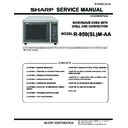
SERVICE MANUAL
R-959(SL)M-AA
CONTENTS
TopPage
S3306R959PKAA
MICROWAVE OVEN WITH
GRILL AND CONVECTION
R-959(SL)M-AA
MODEL
In the interests of user-safety the oven should be restored to its original condition and only parts identical to those spec-
ified should be used.
CONTENTS
CHAPTER 1. BEFORE SERVICING
[1] GENERAL IMPORTANT INFORMA-
[1] GENERAL IMPORTANT INFORMA-
TION ........................................................... 1-1
[2] WARNING
MICROWAVE
RADIATION ....... 1-1
[3] WARNING................................................... 1-1
CHAPTER 2. WARNING TO SERVICE PERSON-
NEL
NEL
CHAPTER 3. PRODUCT SPECIFICATIONS
CHAPTER 4. APPEARANCE VIEW
CHAPTER 5. OPERATION SEQUENCE
[1] OFF
[1] OFF
CONDITION........................................ 5-1
[2] MICROWAVE COOKING CONDITION....... 5-1
[3] GRILL COOKING CONDITION .................. 5-2
[4] CONVECTION
[3] GRILL COOKING CONDITION .................. 5-2
[4] CONVECTION
COOKING
CONDITION..... 5-2
[5] COMBI COOKING CONDITION ................. 5-2
[6] ON/OFF
[6] ON/OFF
TIME
RATIO ................................. 5-2
[7] AUTOMATIC
COOKING ............................. 5-2
[8] POWER OUTPUT REDUCTION ................ 5-3
[9] FAN
[9] FAN
MOTOR
OPERATION......................... 5-3
[10] CONVECTION MOTOR OPERATION........ 5-3
CHAPTER 6. FUNCTION OF IMPORTANT COM-
PONENTS
[1] DOOR OPEN MECHANISM ....................... 6-1
[2] SWITCH...................................................... 6-1
[3] FUSE .......................................................... 6-1
[4] TC
PONENTS
[1] DOOR OPEN MECHANISM ....................... 6-1
[2] SWITCH...................................................... 6-1
[3] FUSE .......................................................... 6-1
[4] TC
TRANSFORMER .................................. 6-1
[5] THERMAL
CUT-OUT.................................. 6-1
[6] ASYMMETRIC
RECTIFIER ........................ 6-1
[7] NOISE
FILTER............................................ 6-2
[8] MOTOR....................................................... 6-2
[9] HEATING
[9] HEATING
ELEMENT .................................. 6-2
[10] CONVECTION COOKING SYSTEM .......... 6-2
[11] FIRE SENSING FEATURE ......................... 6-2
[12] OPEN JUDGE BY THERMISTOR .............. 6-2
[13] DAMPER OPEN-CLOSE MECHANISM..... 6-3
[11] FIRE SENSING FEATURE ......................... 6-2
[12] OPEN JUDGE BY THERMISTOR .............. 6-2
[13] DAMPER OPEN-CLOSE MECHANISM..... 6-3
CHAPTER 7. TROUBLESHOOTING GUIDE
CHAPTER 8. TEST PROCEDURES
[1] A: MAGNETRON TEST .............................. 8-1
[2] B: HIGH VOLTAGE TRANSFORMER
[1] A: MAGNETRON TEST .............................. 8-1
[2] B: HIGH VOLTAGE TRANSFORMER
TEST........................................................... 8-1
[3] C: HIGH VOLTAGE RECTIFIER TEST....... 8-2
[4] D: HIGH VOLTAGE CAPACITOR TEST..... 8-2
[5] E:
[4] D: HIGH VOLTAGE CAPACITOR TEST..... 8-2
[5] E:
SWITCH
TEST ....................................... 8-2
[6] F: THERMISTOR TEST .............................. 8-2
[7] G: THERMAL CUT-OUT TEST................... 8-3
[8] H: MOTOR WINDING TEST ....................... 8-3
[9] I: NOISE FILTER TEST .............................. 8-3
[10] J: BLOWN FUSE 20A ................................. 8-3
[7] G: THERMAL CUT-OUT TEST................... 8-3
[8] H: MOTOR WINDING TEST ....................... 8-3
[9] I: NOISE FILTER TEST .............................. 8-3
[10] J: BLOWN FUSE 20A ................................. 8-3
[11] K: BLOWN FUSE F8A (NOISE FILTER)..... 8-3
[12] L: GRILL HEATING ELEMENTS (TOP)
[12] L: GRILL HEATING ELEMENTS (TOP)
AND CONVECTION HEATING ELE-
MENT TEST................................................ 8-4
MENT TEST................................................ 8-4
[13] M: CONTROL PANEL ASSEMBLY
TEST........................................................... 8-4
[14] N: KEY UNIT TEST..................................... 8-5
[15] O: RELAY TEST ......................................... 8-5
[16] P: PROCEDURES TO BE TAKEN
[15] O: RELAY TEST ......................................... 8-5
[16] P: PROCEDURES TO BE TAKEN
WHEN THE FOIL PATTERN ON THE
PRINTED WIRING BOARD (PWB) IS
OPEN.......................................................... 8-5
PRINTED WIRING BOARD (PWB) IS
OPEN.......................................................... 8-5
CHAPTER 9. TOUCH CONTROL PANEL ASSEM-
BLY
[1] OUTLINE OF TOUCH CONTROL PAN-
BLY
[1] OUTLINE OF TOUCH CONTROL PAN-
EL ............................................................... 9-1
[2] SERVICING FOR TOUCH CONTROL
PANEL ........................................................ 9-2
CHAPTER 10. PRECAUTIONS FOR USING LEAD-
FREE SOLDER
FREE SOLDER
CHAPTER 11. COMPONENT REPLACEMENT
AND ADJUSTMENT PROCEDURE
[1] BEFORE
AND ADJUSTMENT PROCEDURE
[1] BEFORE
OPERATING ..............................11-1
[2] OUTER CASE REMOVAL .........................11-1
[3] HIGH VOLTAGE COMPONENTS RE-
[3] HIGH VOLTAGE COMPONENTS RE-
MOVAL.......................................................11-1
[4] HIGH VOLTAGE TRANSFORMER RE-
MOVAL.......................................................11-2
[5] MAGNETRON
REMOVAL .........................11-2
[6] CONTROL PANEL ASSEMBLY RE-
MOVAL.......................................................11-2
[7] GRAPHIC SHEET AND MEMBRANE
SWITCH REPLACEMENT.........................11-2
[8] FAN
MOTOR
REREPLACEMENT.............11-3
[9] TURNTABLE
MOTOR
REPLACEMENT....11-3
[10] CONVECTION MOTOR AND CONVEC-
TION HEATING ELEMENT REMOVAL .....11-4
[11] POSITIVE LOCK CONNECTOR RE-
MOVAL.......................................................11-4
[12] OVEN LAMP SOCKET REMOVAL ............11-5
[13] POWER SUPPLY CORD REPLACE-
[13] POWER SUPPLY CORD REPLACE-
MENT.........................................................11-5
[14] GRILL HEATING ELEMENTS REMOV-
AL...............................................................11-5
[15] MONITORED LATCH SWITCH, MONI-
TOR SWITCH AND STOP SWITCH RE-
MOVAL.......................................................11-5
MOVAL.......................................................11-5
[16] MONITORED LATCH SWITCH, STOP
SWITCH AND MONITOR SWITCH AD-
JUSTMENT................................................11-6
JUSTMENT................................................11-6
[17] DOOR REPLACEMENT ............................11-6
CHAPTER 12. MICROWAVE MEASUREMENT
CHAPTER 13. CIRCUIT DIAGRAMS
[1] Oven
[1] Oven
Schematic ....................................... 13-1
[2] Pictorial
Diagram ...................................... 13-5
[3] Control
Unit
Circuit.................................... 13-6
[4] Printed Wiring Board ................................ 13-7
Parts List
R-959(SL)M-AA
1 – 1
R959(SL)MA
CHAPTER 1.
BEFORE SERVICING
[1] GENERAL IMPORTANT INFORMATION
This Manual has been prepared to provide Sharp Corp. Service engineers with Operation and Service Information.
It is recommended that service engineers carefully study the entire text of this manual, so they will be qualified to render satisfactory customer ser-
vice.
vice.
[2] WARNING MICROWAVE RADIATION
Personnel should not be exposed to the microwave energy which may radiate from the magnetron or other microwave
generating devices if it is improperly used or connected. All input and output microwave connections, waveguides,
flanges and gaskets must be secured. Never operate the device without a microwave energy absorbing load attached.
Never look into an open waveguide or antenna while the device is energized.
[3] WARNING
Never operate the oven until the following points are ensured.
(A) The door is tightly closed.
(B) The door brackets and hinges are not defective.
(C) The door packing is not damaged.
(D) The door is not deformed or warped.
(E) There is not any other visible damage with the oven.
Servicing and repair work must be carried out only by trained service engineers.
(A) The door is tightly closed.
(B) The door brackets and hinges are not defective.
(C) The door packing is not damaged.
(D) The door is not deformed or warped.
(E) There is not any other visible damage with the oven.
Servicing and repair work must be carried out only by trained service engineers.
All the parts marked "
" on parts list are used at voltages more than 250V.
Removal of the outer wrap gives access to potentials above 250V.
All the parts marked "*" on parts list may cause undue microwave exposure, by themselves, or when they are damaged,
loosened or removed.
Never operate the Grill and/ or Convection heater with the oven outer cabinet removed. (Because air flow is elim-
inated, and the excess heat generated on adjacent components). It can cause permanent damage or a fire.
WARNING: THIS APPLIANCE MUST BE EARTHED
IMPORTANT
THE WIRES IN THIS MAINS LEAD ARE COLOURED IN ACCORDANCE WITH THE FOLLOWING CODE:
GREEN-AND-YELLOW--------------EARTH
BLUE---------------------------------NEUTRAL
BROWN-------------------------------------LIVE
BROWN-------------------------------------LIVE


