Sharp R-899SL (serv.man5) Service Manual ▷ View online
R899(WH)
5 – 3
3. The relay RY3 is energized and the main supply voltage is applied
to the top grill heating element.
4. The relay RY2 is energized and the microwave energy is generated
by magnetron.
5. Now, the food is cooked by microwave and top grill simultaneously.
3. MICROWAVE AND BOTTOM GRILL (Figure O-5c)
Rotate the COOKING MODE dial to
COMBI 3 setting. And enter
the desired cooking time by rotating the TIME/WEIGHT dial. And press
MICROWAVE POWER LEVEL button to set the desired microwave
power. When the START button is pressed, the following operations
occur:
MICROWAVE POWER LEVEL button to set the desired microwave
power. When the START button is pressed, the following operations
occur:
1. The numbers on the digital readout start the count down to zero.
2. The oven lamp, cooling fan motor and turntable motor are ener-
gized.
3. The relay RY4 is energized and the main supply voltage is applied
to the bottom grill heating element.
4. The relay RY2 is energized and the microwave energy is generated
by magnetron.
5. Now, the food is cooked by microwave and bottom grill simulta-
neously.
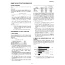
[6] ON/OFF TIME RATIO
In grill cooking, convection cooking or combi cooking, the top heater,
bottom heater or magnetron operate within a 54 second time base.
The following table is the ON / OFF time ratio at each power output of
the top heaters, bottom heater or magnetron.
bottom heater or magnetron operate within a 54 second time base.
The following table is the ON / OFF time ratio at each power output of
the top heaters, bottom heater or magnetron.
[7] AUTO POWER CONTROL OPERATION
The magnetron, top or bottom heating elements, the fan motor or the convection motor will operate in accordance with following specification.
1. OUTPUT POWER CONTROL (MANUAL COOK)
2. OUTPUT POWER CONTROL (AUTO COOK)
POWER OUTPUT
ON TIME
OFF TIME
100%
54 sec.
0 sec.
90%
49 sec.
5 sec.
80%
45 sec.
9 sec.
70%
40 sec.
14 sec.
60%
36 sec.
18 sec.
50%
29 sec.
25 sec.
40%
24 sec.
30 sec.
30%
18 sec.
36 sec.
20%
13 sec.
41 sec.
10%
9 sec.
45 sec.
OPERATION MODE
DEVICE
POWER CONTROL
MICROWAVE (100%)
SINGLE OPERATION
SINGLE OPERATION
Microwave
100% 20min, then 70%
TOP GRILL (100%)
SINGLE OPERATION
SINGLE OPERATION
Top heater
100% 15min, then 50%
BOTTOM GRILL (100%)
SINGLE OPERATION
SINGLE OPERATION
Bottom heater
100% 15min, then 50%
TOP(100%)/BOTTOM(100%)
COMBI OPERATION
COMBI OPERATION
Top heater
100% 6min then 70% and 70% 9min then 50%
Bottom heater
100% 6min then 70% and 70% 9min then 50%
MICRO(100%)/TOP GRILL(100%)
COMBI OPERATION
COMBI OPERATION
Microwave
100% 20min, then 70%
Top heater
100% 15min, then 50%
MICRO(70 - 10%)/TOP GRILL(100%)
COMBI OPERATION
COMBI OPERATION
Microwave
-
Top heater
100% 15min, then 50%
MICRO(100%)/BOTTOM GRILL(100%)
COMBI OPERATION
COMBI OPERATION
Microwave
100% 20min, then 70%
Bottom heater
100% 15min, then 50%
MICRO(70 - 10%)/BOTTOM GRILL(100%)
COMBI OPERATION
COMBI OPERATION
Microwave
-
Bottom heater
100% 15min, then 50%
Repeat Cook
Microwave
Top heater
Bottom heater
Top heater
Bottom heater
In case same cooking mode is repeated within 1min 15sec (including stop, end),
oven calculates total cooking time and reduce the power level.
oven calculates total cooking time and reduce the power level.
OPERATION MODE
DEVICE
POWER CONTROL
Repeat Auto Cook
Microwave
The power level is not reduced 1 time cooking. But only in case same menu is
repeated within 1min 15sec, the power level of micro and grill is reduced from
100% to 70% in 20mins after starting of last cooking. (Even if the time of the last
cooking is longer than 20mins, the power level isn't reduced on the last cooking,
and it is reduced from the beginning of the next cooking.) However, in time calcu-
lated from the start of the 1st cooking, even if the Cook mode changed, when rep-
etition cooking of the menu with which 100% of top & bottom heaters continues
are performed, as shown in the following table, the power down of the cooking of
the 2nd henceforth is carried out. (The 1st cooking is not applied)
R899(WH)
5 – 4
3. COOLING FAN OPERATION
4. CONVECTION POWER SETTING
4.1. PREHEATING
4.2. CONVECTION
4.3. COMBI-1 (Micro + Conv)
NOTE:
✩The oven temp was checked by the thermometer when each stage is started.
If the oven temp is same or higher than 105
If the oven temp is same or higher than 105
°C, the oven was judged as "with preheating".
When the oven temp is lower than 105
Micro and Top heating element can't be on at the same time.
OPERATION MODE
DEVICE
POWER CONTROL
PREHEAT
Cooling
60%
CONV. (OVEN)
Cooling fan
60% 60 min. then 100%
Others
Cooling fan
100%
After cooking
Cooling fan
A cooling fan continues the rotation when Oven temperature is more than 120
°C.
Then, it stops when it is less than 105
°C
Indication
NOW COOLING is indicated during the cooling fan movement after operation is
finished. (It isn't indicated during a fan movement to stop on the way.)
finished. (It isn't indicated during a fan movement to stop on the way.)
TEMP
250
°C, 230°C, 220°C, 200°C, 180°C, 160°C, 130°C, 100°C, 70°C, 40°C
HEATING ELEMENT
TOP 100%
BOTTOM
BOTTOM
100%
COOLING FAN
60%
CONV. FAN
0%
TEMP
250
°C
230
°C
220
°C
200
°C
180
°C
160
°C
130
°C 100°C
70
°C
40
°C
✩WITHOUT PREHEATING
HEATING
ELEMENT
ELEMENT
TOP
50%
40%
40%
30%
20%
10%
10%
10%
10%
10%
BOTTOM
100%
90%
80%
70%
70%
60%
50%
40%
30%
20%
✩WITH PREHEATING
HEATING
ELEMENT
ELEMENT
TOP
50%
40%
40%
30%
20%
10%
10%
10%
10%
10%
BOTTOM
90%
70%
60%
50%
50%
50%
50%
40%
30%
20%
COOLING FAN
60% 60min, then 100%
CONV. FAN
100%
0%
TEMP
250
°C
230
°C
220
°C
200
°C
180
°C
160
°C
130
°C
100
°C
70
°C
40
°C
✩WITHOUT PREHEATING
HEATING
ELEMENT
ELEMENT
TOP
50%
40%
40%
30%
20%
10%
10%
10%
10%
10%
BOTTOM
100%
90%
80%
70%
70%
60%
50%
40%
30%
20%
✩WITH PREHEATING
HEATING
ELEMENT
ELEMENT
TOP
50%
40%
40%
30%
20%
10%
10%
10%
10%
10%
BOTTOM
90%
70%
60%
50%
50%
50%
50%
40%
30%
20%
MICRO
10%, 30%, 50%
COOLING FAN
100%
CONV. FAN
100%
0%
Display

