Sharp R-895M (serv.man7) Service Manual ▷ View online
R-895M - 19
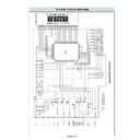
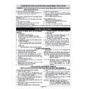
The touch control section consists of the following units as
shown in the touch control panel circuit.
shown in the touch control panel circuit.
(1) Key Unit
(2) Control Unit (The Control unit consists of Power unit
(2) Control Unit (The Control unit consists of Power unit
and CPU unit.)
The principal functions of these units and signals commu-
nicated among them are explained below.
nicated among them are explained below.
Key Unit
The key unit is composed of a matrix, signals generated in
the LSI are sent to the key unit from P40, P41, P72, P73,
P74, P75, P76 and P77.
When a key pad is touched, a signal is completed through
the key unit and passed back to the LSI through P50 - P53
to perform the function that was requested.
The key unit is composed of a matrix, signals generated in
the LSI are sent to the key unit from P40, P41, P72, P73,
P74, P75, P76 and P77.
When a key pad is touched, a signal is completed through
the key unit and passed back to the LSI through P50 - P53
to perform the function that was requested.
Control Unit
Control unit consists of LSI, power source circuit, synchro-
nizing signal circuit, reset circuit, buzzer circuit, relay
circuit, temperature measurement circuit, indicator circuit
and back light circuit.
Control unit consists of LSI, power source circuit, synchro-
nizing signal circuit, reset circuit, buzzer circuit, relay
circuit, temperature measurement circuit, indicator circuit
and back light circuit.
1) LSI
This LSI controls the temperature measurement sig-
nal, key strobe signal, relay driving signal for oven
function and indicator signal.
nal, key strobe signal, relay driving signal for oven
function and indicator signal.
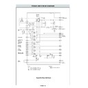
2) Power Source Circuit
This circuit generates voltage necessary in the control
unit.
unit.
Symbol
Voltage
Application
VC
-5.2V
LSI(IC1)
3) Synchronizing Signal Circuit
The power source synchronizing signal is available in
order to compose a basic standard time in the clock
circuit. It accompanies a very small error because it
works on commercial frequency.
order to compose a basic standard time in the clock
circuit. It accompanies a very small error because it
works on commercial frequency.
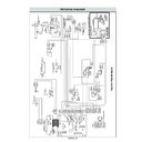
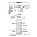
TOUCH CONTROL PANEL ASSEMBLY
OUTLINE OF TOUCH CONTROL PANEL
4) Reset Circuit
A circuit to generate a signal which resets the LSI to the
initial state when power is supplied.
initial state when power is supplied.
5) Buzzer Circuit
The buzzer is responsive to signals from the LSI to emit
audible sounds (key touch sound and completion
sound).
audible sounds (key touch sound and completion
sound).
6) Stop Switch
A switch to “tell” the LSI if the door is open or closed.
7) Relay Circuit
To drive the magnetron, grill heating element, bottom
heating element, convection motor, fan motor, turnta-
ble motor, touch control transformer and light the oven
lamp.
heating element, convection motor, fan motor, turnta-
ble motor, touch control transformer and light the oven
lamp.
8) Back Light Circuit
A circuit to drive the back light (Light emitting diodes
LD1 - LD10).
LD1 - LD10).
9) Indicator Circuit
This circuit consists 7-digits, 39-segments and 3-com-
mon electrodes using a Liquid Crystal Display.
mon electrodes using a Liquid Crystal Display.
10)Temperature Measurement Circuit : (OVEN THER-
MISTOR)
The temperature in the oven cavity is sensed by the
thermistor. The variation of resistance according to
sensed temperature is detected by the temperature
measurement circuit and the result applied to LSI. The
LSI uses this information to control the relay and
display units.
The temperature in the oven cavity is sensed by the
thermistor. The variation of resistance according to
sensed temperature is detected by the temperature
measurement circuit and the result applied to LSI. The
LSI uses this information to control the relay and
display units.
R-895M - 20
8
AN2
IN
Input signal which communicates the door open/close information to LSI.
Door closed; “H” level signal.
Door opened; “L” level signal.
Door closed; “H” level signal.
Door opened; “L” level signal.
9
AN1
IN
Heating constant compensation terminal.
10
AN0
IN
Terminal to change functions to the Models.
11
P57
OUT
Timing signal output terminal for temperature measurement(OVEN
THERMISTOR).
“H” level (GND) : Thermistor OPEN timing.
“L” level (-5V) : Temperature measuring timing. (Oven cooking)
THERMISTOR).
“H” level (GND) : Thermistor OPEN timing.
“L” level (-5V) : Temperature measuring timing. (Oven cooking)
12
P56
OUT
Terminal not used.
13
P55
OUT
Timing signal output terminal for temperature measurement(OVEN
THERMISTOR).
“H” level (GND) : Thermistor OPEN timing.
“L” level (-5V) : Temperature measuring timing. (Oven cooking)
THERMISTOR).
“H” level (GND) : Thermistor OPEN timing.
“L” level (-5V) : Temperature measuring timing. (Oven cooking)
14
P54
OUT
Terminal not used.
15
P53
IN
Signal coming from touch key.
When any one of G12 line keys on key matrix is touched, a corresponding signal
from P40, P41, P72, P73, P74, P75, P76 and P77 will be input into P53. When no
key is touched, the signal is held at “L” level.
When any one of G12 line keys on key matrix is touched, a corresponding signal
from P40, P41, P72, P73, P74, P75, P76 and P77 will be input into P53. When no
key is touched, the signal is held at “L” level.
16
P52
IN
Signal similar to P53.
When any one of G11 line keys on key matrix is touched, a corresponding signal
will be input into P52.
When any one of G11 line keys on key matrix is touched, a corresponding signal
will be input into P52.
17
P51
IN
Signal similar to P53.
When any one of G10 line keys on key matrix is touched, a corresponding signal
will be input into P51.
When any one of G10 line keys on key matrix is touched, a corresponding signal
will be input into P51.
18
P50
IN
Signal similar to P53.
When any one of G9 line keys on key matrix is touched, a corresponding signal will
be input into P50.
When any one of G9 line keys on key matrix is touched, a corresponding signal will
be input into P50.
19-22
P47-P44
IN/OUT
Terminal not used.
23
TOUT
OUT
Signal to sound buzzer.
A: Tact switch touch sound.
B: Completion sound.
C: When the temperature of the oven cavity
A: Tact switch touch sound.
B: Completion sound.
C: When the temperature of the oven cavity
reaches the preset temperature in the
preheating mode, or when the
preheating hold time (30 minutes) is
elapsed.
preheating mode, or when the
preheating hold time (30 minutes) is
elapsed.
24
INT2
IN
Signal to synchronized LSI with commercial power source frequency(50Hz).
This is basic timing for time processing of LSI.
This is basic timing for time processing of LSI.
25
P41
OUT
Key strobe signal.
Signal applied to touch-key section. A pulse signal is input to P50-P53 terminal
while one of G8 line key on matrix is touched.
Signal applied to touch-key section. A pulse signal is input to P50-P53 terminal
while one of G8 line key on matrix is touched.
A
B
C
H : GND
L
0.1 sec.
2.0 sec.
1.0 sec.
1.0 sec.
20 msec.
H : GND
L (-5V)
Pin No.
Signal
I/O
Description
DESCRIPTION OF LSI
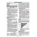
The I/O signal of the LSI are detailed in the following table.
1
C1
IN
Terminal not used.
2
VL1
IN
Power source voltage input terminal.
Standard voltage for LCD.
Standard voltage for LCD.
3
AN7
IN
Terminal to change the on timing of the cook relay (RY2).
4-5
AN6-AN5
IN
Heating constant compensation terminal.
6
AN4
OUT
Terminal not used.
7
AN3
IN
Temperature measurement input: OVEN THERMISTOR.
By inputting DC voltage corresponding to the temperature detected by the
thermistor, this input is converted into the temperature by the A/D converter built
into the LSI.
By inputting DC voltage corresponding to the temperature detected by the
thermistor, this input is converted into the temperature by the A/D converter built
into the LSI.
R-895M - 21
Pin No.
Signal
I/O
Description
26
P40
OUT
Key strobe signal.
Signal applied to touch-key section. A pulse signal is input to P50-P53 terminal
while one of G7 line key on matrix is touched.
Signal applied to touch-key section. A pulse signal is input to P50-P53 terminal
while one of G7 line key on matrix is touched.
27
P77
OUT
Key strobe signal.
Signal applied to touch-key section. A pulse signal is input to P50-P53 terminal
while one of G6 line key on matrix is touched.
Signal applied to touch-key section. A pulse signal is input to P50-P53 terminal
while one of G6 line key on matrix is touched.
28
P76
OUT
Key strobe signal.
Signal applied to touch-key section. A pulse signal is input to P50-P53 terminal
while one of G5 line key on matrix is touched.
Signal applied to touch-key section. A pulse signal is input to P50-P53 terminal
while one of G5 line key on matrix is touched.
29
P75
OUT
Key strobe signal.
Signal applied to touch-key section. A pulse signal is input to P50-P53 terminal
while one of G4 line key on matrix is touched.
Signal applied to touch-key section. A pulse signal is input to P50-P53 terminal
while one of G4 line key on matrix is touched.
30
P74
OUT
Key strobe signal.
Signal applied to touch-key section. A pulse signal is input to P50-P53 terminal
while one of G3 line key on matrix is touched.
Signal applied to touch-key section. A pulse signal is input to P50-P53 terminal
while one of G3 line key on matrix is touched.
31
P73
OUT
Key strobe signal.
Signal applied to touch-key section. A pulse signal is input to P50-P53 terminal
while one of G2 line key on matrix is touched.
Signal applied to touch-key section. A pulse signal is input to P50-P53 terminal
while one of G2 line key on matrix is touched.
32
P72
OUT
Key strobe signal.
Signal applied to touch-key section. A pulse signal is input to P50-P53 terminal
while one of G1 line key on matrix is touched.
Signal applied to touch-key section. A pulse signal is input to P50-P53 terminal
while one of G1 line key on matrix is touched.
33
P71
IN/OUT
Terminal not used.
34
P70
IN
Connected to VC.
35
RESET
IN
Auto clear terminal.
Signal is input to reset the LSI to the initial state when power is applied. Temporarily
set to “L” level the moment power is applied, at this time the LSI is reset. Thereafter
set at “Hµ…level.
Signal is input to reset the LSI to the initial state when power is applied. Temporarily
set to “L” level the moment power is applied, at this time the LSI is reset. Thereafter
set at “Hµ…level.
36
XCIN
IN
Connected to VC.
37
XCOUT
OUT
Terminal not used.
38
XIN
IN
Internal clock oscillation frequency input setting.
The internal clock frequency is set by inserting the ceramic filter oscillation circuit
with respect to XOUT terminal.
The internal clock frequency is set by inserting the ceramic filter oscillation circuit
with respect to XOUT terminal.
39
XOUT
OUT
Internal clock oscillation frequency control output.
Output to control oscillation input of XIN.
Output to control oscillation input of XIN.
40
VSS
IN
Power source voltage: -5V.
VC voltage of power source circuit input.
VC voltage of power source circuit input.
41
P27
OUT
Bottom heating element driving signal.
To turn on and off the relay (RY4). “L” level during grill
cooking, convection cooking or dual cooking, “H”
level otherwise. The heater relay turns on and off
within a 54 second time base in accordance with the
special program in LSI.
To turn on and off the relay (RY4). “L” level during grill
cooking, convection cooking or dual cooking, “H”
level otherwise. The heater relay turns on and off
within a 54 second time base in accordance with the
special program in LSI.
42
P26
OUT
Convection motor driving signal.
To turn on and off shut-off relay (RY7). “L” level
during convection or dual cooking, “H” level otherwise.
(Relay RY7 does not turn on at preheating mode.)
To turn on and off shut-off relay (RY7). “L” level
during convection or dual cooking, “H” level otherwise.
(Relay RY7 does not turn on at preheating mode.)
43
P25
OUT
Fan motor driving signal.
To turn on and off the fan motor relay (RY6).
“L” level during cooking, or for a while after
convection or dual cooking. “H” level otherwise.
To turn on and off the fan motor relay (RY6).
“L” level during cooking, or for a while after
convection or dual cooking. “H” level otherwise.
44
P24
OUT
Terminal not used.
45
P23
OUT
Touch control transformer driving signal.
To turn on and off the shut off relay (RY5). If the oven has not been used for more
than 2 minutes, the relay RY5 will be turned off. The relay RY5 will be turned on
when the oven door is opened and closed.
To turn on and off the shut off relay (RY5). If the oven has not been used for more
than 2 minutes, the relay RY5 will be turned off. The relay RY5 will be turned on
when the oven door is opened and closed.
ON
OFF
During
cooking
L
GND
H.
(Grill, Convection, Dual )
ON
OFF
During
cooking
L
GND
H.
( Convection or Dual cooking )
ON
OFF
During cooking, or for a while
after convection or dual cooking.
L
GND
H.
The I/O signal of the LSI are detailed in the following table.
DESCRIPTION OF LSI
R-895M - 22
46
P22
OUT
Magnetron high-voltage circuit driving signal.
To turn on and off the cook relay
(RY2). In 100% operation, the
signals hold “L” level during
microwave cooking and “H” level
while not cooking. In other
cooking modes (70%, 50%, 30%,
10%) the signal turns to “H” level
and “L” level in repetition
according to the power level.
To turn on and off the cook relay
(RY2). In 100% operation, the
signals hold “L” level during
microwave cooking and “H” level
while not cooking. In other
cooking modes (70%, 50%, 30%,
10%) the signal turns to “H” level
and “L” level in repetition
according to the power level.
47
P21
OUT
Grill (TOP) heating element driving signal.
To turn on and off the grill heating element relay
(RY3). “L” level during grill cooking, convection
cooking or dual cooking. “H” level otherwise. The
heater relay turns on and off within a 54 second time
base in accordance with the special progrom in LSI.
To turn on and off the grill heating element relay
(RY3). “L” level during grill cooking, convection
cooking or dual cooking. “H” level otherwise. The
heater relay turns on and off within a 54 second time
base in accordance with the special progrom in LSI.
48
P20
OUT
Oven lamp and turntable motor driving signal(Square Waveform : 50Hz).
To turn on and off shut-off relay (RY1).
The square waveform voltage is
delivered to the relay (RY1) driving
circuit.
To turn on and off shut-off relay (RY1).
The square waveform voltage is
delivered to the relay (RY1) driving
circuit.
49-50
P17-P16
OUT
Terminal not used.
51-80
SEG39-SEG10
OUT
Segment data signal.
Connected to LCD.
The relation between signals are as follows:
Connected to LCD.
The relation between signals are as follows:
LSI signal (Pin No.)
LCD (Pin No.)
LSI signal (Pin No.) LCD (Pin No.)
SEG 0 (90) ....................SEG39 (51)
SEG21 (69) ................. SEG19 (19)
SEG 1 (89) ....................SEG38 (50)
SEG22 (68) ................. SEG18 (18)
SEG 2 (88) ....................SEG37 (49)
SEG23 (67) ................. SEG17 (17)
SEG 3 (87) ....................SEG36 (48)
SEG24 (66) ................. SEG16 (16)
SEG 4 (86) ....................SEG35 (47)
SEG25 (65) ................. SEG15 (15)
SEG 5 (85) ....................SEG34 (46)
SEG26 (64) ................. SEG14 (14)
SEG 6 (84) ....................SEG33 (45)
SEG27 (63) ................. SEG13 (13)
SEG 7 (83) ....................SEG32 (44)
SEG28 (62) ................. SEG12 (12)
SEG 8 (82) ....................SEG31 (43)
SEG29 (61) ................. SEG11 (11)
SEG10 (80) ...................SEG30 (30)
SEG30 (60) ................. SEG10 (10)
SEG11 (79) ...................SEG29 (29)
SEG31 (59) ................... SEG 9 ( 9)
SEG12 (78) ...................SEG28 (28)
SEG32 (58) ................... SEG 8 ( 8)
SEG13 (77) ...................SEG27 (27)
SEG33 (57) ................... SEG 7 ( 7)
SEG14 (76) ...................SEG26 (26)
SEG34 (56) ................... SEG 6 ( 6)
SEG15 (75) ...................SEG25 (25)
SEG35 (55) ................... SEG 5 ( 5)
SEG16 (74) ...................SEG24 (24)
SEG36 (54) ................... SEG 4 ( 4)
SEG17 (73) ...................SEG23 (23)
SEG37 (53) ................... SEG 3 ( 3)
SEG18 (72) ...................SEG22 (22)
SEG38 (52) ................... SEG 2 ( 2)
SEG19 (71) ...................SEG21 (21)
SEG39 (51) ................... SEG 1 ( 1)
SEG20 (70) ...................SEG20 (20)
81
SEG9
OUT
Terminal not used.
82-90
SEG8-SEG0
OUT
Segment data signal.
Connected to LCD. Signal is similar to SEG39.
Connected to LCD. Signal is similar to SEG39.
91
VCC
IN
Connected to GND.
92
VREF
IN
Connected to GND.
93
AVSS
IN
Connected to VC.
94
COM3
OUT
Terminal not used.
95
COM2
OUT
Common data signal: COM3.
Connected to LCD (Pin No. 35).
Connected to LCD (Pin No. 35).
96
COM1
OUT
Common data signal: COM2.
Connected to LCD (Pin No. 34).
Connected to LCD (Pin No. 34).
97
COM0
OUT
Common data signal: COM1.
Connected to LCD (Pin No. 33).
Connected to LCD (Pin No. 33).
98-99
VL3-VL2
IN
Power source voltage input terminal.
Standard voltage for LCD.
Standard voltage for LCD.
100
C2
IN
Terminal not used.
Pin No.
Signal
I/O
Description
During cooking
L
H
20 msec.
ON
OFF
During
cooking
L
GND
H.
(Grill, Convection, Dual )
MICRO
ON
OFF
COOK
100%
54 sec.
0 sec.
70%
40 sec.
14 sec.
50%
29 sec.
25 sec.
30%
18 sec.
36 sec.
10%
9 sec.
45 sec.
MICRO
ON
OFF
COOK
100%
32 sec.
0 sec.
70%
24 sec.
8 sec.
50%
18 sec.
14 sec.
30%
12 sec.
20 sec.
10%
6 sec.
26 sec.
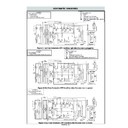
ON/OFF time ratio in Micro
cooking
(a. 32second time base)
(a. 32second time base)
ON/OFF time ratio in Micro
cooking
(a. 54second time base)
(a. 54second time base)
The I/O signal of the LSI are detailed in the following table.
DESCRIPTION OF LSI
Display

