Sharp R-67STM (serv.man5) Service Manual ▷ View online
R67STM
5 – 1
R67STM
Service Manual
CHAPTER 5.
OPERATION SEQUENCE
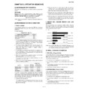
[1] MICROWAVE OFF CONDITION
Closing the door activates the door interlock switch (monitored latch
switch).
switch).
IMPORTANT
When the oven door is closed, the the monitor switch contacts
COM-NC must be open. When the microwave oven is plugged in a
wall outlet (230-240V / 50Hz), the noise filter is energised.
COM-NC must be open. When the microwave oven is plugged in a
wall outlet (230-240V / 50Hz), the noise filter is energised.
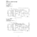
Figure O-1 on page 13-1
NOTE: When the oven door is opened, the oven lamp comes on at
this time.
[2] MICROWAVE COOKING CONDITION
1. HIGH COOKING
Enter a desired cooking time by pressing the TIME keys. And press
MICROWAVE POWER key once. Then start the oven by pressing
START key.
MICROWAVE POWER key once. Then start the oven by pressing
START key.
Function sequence
Figure O-2 on page 13-1
1. The line voltage is supplied to the primary winding of the high volt-
age transformer T. The voltage is converted to about 3.3 volts A.C.
output on the filament winding and high voltage of approximately
2000 volts A.C. on the secondary winding.
output on the filament winding and high voltage of approximately
2000 volts A.C. on the secondary winding.
2. The filament winding voltage (3.3 volts) heats the magnetron fila-
ment and the high voltage (2000 volts) is sent to the voltage dou-
bling circuit, where it is doubled to negative voltage of
approximately 4000 volts D.C..
bling circuit, where it is doubled to negative voltage of
approximately 4000 volts D.C..
3. The 2450 MHz microwave energy produced in the magnetron gen-
erates a wavelength of 12.24cm. This energy is channelled through
the waveguide (transport channel) into the oven cavity, where the
food is placed to be cooked.
the waveguide (transport channel) into the oven cavity, where the
food is placed to be cooked.
4. When the cooking time is up, a signal tone is heard and the relays
RY1 + RY3 + RY4 go back to their home position.
The circuits to the oven lamp high voltage transformer, fan motor
and turntable motor are cut off.
and turntable motor are cut off.
5. When the oven door is opened during a cooking cycle, the switches
come to the following condition.
The circuit to the high voltage transformer, fan motor and turntable
motor are cut off when the monitored latch switch is open. The oven
lamp remains on even if the oven door is opened after the cooking
cycle has been interrupted, because the relay RY1 stays closed.
Shown in the display is the remaining time.
motor are cut off when the monitored latch switch is open. The oven
lamp remains on even if the oven door is opened after the cooking
cycle has been interrupted, because the relay RY1 stays closed.
Shown in the display is the remaining time.
6. MONITOR SWITCH CIRCUIT
The monitor switch is mechanically controlled by the oven door,
and monitors the operation of the monitored latch switch, the relay
RY1 and the relay RY3.
and monitors the operation of the monitored latch switch, the relay
RY1 and the relay RY3.
1) When the oven door is opened during or after the cycle of a
cooking program, the monitored latch switch and stop switch
must open their contacts (COM-NO) first. After that the contacts
(COM - NC) of the monitor switch can be closed.
must open their contacts (COM-NO) first. After that the contacts
(COM - NC) of the monitor switch can be closed.
2) When the oven door is closed, the contacts (COM - NC) of the
monitor switch must be opened first. The contacts (COM - NO)
of the monitored latch switch and stop switch are closed after.
of the monitored latch switch and stop switch are closed after.
3) When the oven door is opened and the contacts of the moni-
tored latch switch, the relay RY1 and the relay RY3 remain
closed, the fuse F8A will blow, because the monitor switch is
closed and a short circuit is caused.
closed, the fuse F8A will blow, because the monitor switch is
closed and a short circuit is caused.
2. MEDIUM HIGH, MEDIUM, MEDIUM LOW, LOW
COOKING
COOKING
When the microwave oven is preset for variable cooking power, the
line voltage is supplied to the high voltage transformer T intermittently
within a 32-second time base through the vari contact. The following
levels of microwave power are given.
line voltage is supplied to the high voltage transformer T intermittently
within a 32-second time base through the vari contact. The following
levels of microwave power are given.
SETTING;
NOTE: The ON/OFF time ratio does not exactly correspond to the
percentage of microwave power, because approx. 3 seconds
are needed for heating up the magnetron filament.
are needed for heating up the magnetron filament.
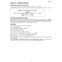
[3] GRILL COOKING CONDITION
1. TOP GRILL (Figure O-3(a))
In this condition the food is cooked by the grill heating element energy.
Enter the grilling time by pressing the TIME keys. And then press the
GRILL key once and start the oven by pressing START key.
Enter the grilling time by pressing the TIME keys. And then press the
GRILL key once and start the oven by pressing START key.
The following operations occur:
1. The numbers on the display start the count down to zero.
2. The oven lamp, cooling fan motor and turntable motor are ener-
gized.
3. The relay RY2 is energized and the main supply voltage is applied
to the grill heating element.
4. Now, the food is cooked by the grill heating element.
2. BOTTOM GRILL (Figure O-3(b))
In this condition the food is cooked by the bottom heating element
energy. Enter the grilling time by pressing the TIME keys. And then
press the GRILL key twice and start the oven by pressing START key.
energy. Enter the grilling time by pressing the TIME keys. And then
press the GRILL key twice and start the oven by pressing START key.
The following operations occur:
1. The numbers on the display start the count down to zero.
2. The oven lamp, cooling fan motor and turntable motor are ener-
gized.
3. The relay RY5 is energized and the main supply voltage is applied
to the bottom heating element.
4. Now, the food is cooked by the bottom heating element.
CONNECTED COMPONENTS
RELAY
Oven lamp, Turntable motor
RY1
High voltage transformer
RY3
Fan motor,
RY4
CONDITION
SWITCH CONTACT
DURING
COOKING
DOOR OPEN
(NO COOKING)
Monitor switch
COM-NC
Opened
Closed
Monitored latch
switch
switch
COM-NO Closed
Opened
Stop switch
COM-NO
Closed
Opened
100P(HIGH)
32 sec. ON
70P
(MEDIUM HIGH)
Approx. 70%
100%
24 sec. ON
8 sec. OFF
14 sec. OFF
20 sec. OFF
26 sec. OFF
50P(MEDIUM)
Approx. 50%
18 sec. ON
30P
(MEDIUM LOW)
Approx. 30%
12 sec. ON
10P(LOW)
Approx. 10%
6 sec. ON
R67STM
5 – 2
3. GRILL (Figure O-3(c))
In this condition the food is cooked by the top and bottom heating ele-
ments energy. Enter the grilling time by pressing the TIME keys. And
then press the GRILL key three times and start the oven by pressing
START key.
ments energy. Enter the grilling time by pressing the TIME keys. And
then press the GRILL key three times and start the oven by pressing
START key.
The following operations occur:
1. The numbers on the display start the count down to zero.
2. The oven lamp, cooling fan motor and turntable motor are ener-
gized.
3. The relays RY2 and RY5 are energized and the main supply volt-
age is applied to the top and bottom heating elements.
4. Now, the food is cooked by the top and bottom heating elements.
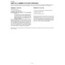
[4] DUAL COOKING CONDITION
1. DUAL 1 (Figure O-4(a))
In this condition the food is cooked by the microwave energy and top
heating element energy. Enter the desired cooking time by rpressing
the TIME keys. And then press the DUAL GRILL key once and start
the oven by pressing START key.
heating element energy. Enter the desired cooking time by rpressing
the TIME keys. And then press the DUAL GRILL key once and start
the oven by pressing START key.
The following operations occur:
1. The numbers on the display start the count down to zero.
2. The oven lamp, cooling fan motor and turntable motor are ener-
gized.
3. The relay RY2 is energized and the main supply voltage is applied
to the top heating element.
4. The relay RY3 is energized and the microwave energy is generated
by magnetron.
5. Now, the food is cooked by the magnetron and the top heating ele-
ment.
2. DUAL 2 (Figure O-4(b))
In this condition the food is cooked by the microwave energy and bot-
tom heating element energy. Enter the desired cooking time by press-
ing the TIME keys. And then press the DUAL GRILL key twice and
start the oven by pressing START key.
tom heating element energy. Enter the desired cooking time by press-
ing the TIME keys. And then press the DUAL GRILL key twice and
start the oven by pressing START key.
The following operations occur:
1. The numbers on the display start the count down to zero.
2. The oven lamp, cooling fan motor and turntable motor are ener-
gized.
3. The relay RY5 is energized and the main supply voltage is applied
to the bottom heating element.
4. The relay RY3 is energized and the microwave energy is generated
by magnetron.
5. Now, the food is cooked by the magnetron and the bottom heating
element.
[5] FAN MOTOR OPERATION (in Grill and
Dual cooking)
Dual cooking)
Upon completion of the selected cooking time, the fan motor FM con-
tinues to operate for 2 minutes (in case that the oven has been oper-
ated for more than 3 minutes in Grill or Dual Grill cooking condition).
tinues to operate for 2 minutes (in case that the oven has been oper-
ated for more than 3 minutes in Grill or Dual Grill cooking condition).
[6] ON/OFF TIME RATIO
In grill cooking or dual cooking, the top heater, bottom heater or mag-
netron operate within a 54 second time base.
netron operate within a 54 second time base.
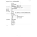
[7] POWER CONTROL OPERATION
The magnetron, top or bottom heating elements or the fan motor will operate in accordance with following specification.
OPERATION MODE
DEVICE
POWER CONTROL
MICROWAVE SINGLE OPERATION
Microwave
100% 20min, then 70%
TOP GRILL SINGLE OPERATION
Top heating element
100 – 70% 10min, then 50%
BOTTOM GRILL SINGLE OPERATION
Bottom heating element
100 – 70% 10min, then 50%
TOP AND BOTTOM OPERATION
Top heating element
100% 5min then 70% and 70% 5min then 50%
Bottom heating element
100 – 70% 5min, then 50%
TOP GRILL and MICROWAVE OPERATION
Microwave
70% 10min, then 50%
Top heating element
100 – 70% 10min, then 50%
BOTTOM GRILL and MICROWAVE OPERATION
Microwave
70% 10min, then 50%
Bottom heating element
100 – 70% 10min, then 50%
Display

