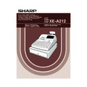
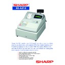
Sharp XE-A212 Service Manual ▷ View online
CODE : 00Z
q
SERVICE MANUAL
CONTENTS
Parts marked with "
!
" are important for maintaining the safety of the set. Be sure to replace these parts with specified
ones for maintaining the safety and performance of the set.
SHARP CORPORATION
XEA212VSME
ELECTRONIC
CASH REGISTER
CASH REGISTER
MODEL
XE-A212
(V version)
CHAPTER 1. SPECIFICATIONS . . . . . . . . . . . . . . . . . . . . . . . . . . . . 1
CHAPTER 2. OPTIONS . . . . . . . . . . . . . . . . . . . . . . . . . . . . . . . . . . . 5
CHAPTER 3. MASTER RESET AND PROGRAM RESET. . . . . . . . . 5
CHAPTER 4. HARDWARE DESCRIPTION . . . . . . . . . . . . . . . . . . . . 6
CHAPTER 5. DIAGNOSTIC PROGRAM . . . . . . . . . . . . . . . . . . . . . 12
CHAPTER 6. IPL FROM EP-ROM . . . . . . . . . . . . . . . . . . . . . . . . . . 16
CHAPTER 7. CAUTION TO BE USED WHEN
CONNECTING THE RS-232 CABLE . . . . . . . . . . . . . 16
CHAPTER 8. CIRCUIT DIAGRAM AND PWB LAYOUT . . . . . . . . . 17
XE-A212V
SPECIFICATIONS
– 1 –
CHAPTER 1. SPECIFICATIONS
1. APPEARANCE
2. RATING
3. KEYBOARD
1) KEYBOARD LAYOUT
2) KEY LIST
■
■
■
■
Keyboard layout
■
■
■
■
Key names
4. MODE SWITCH
1) LAYOUT
• Rotary type
The mode switch can be operated by inserting one of the two supplied
mode keys - manager (MA) and operator (OP) keys. These keys can be
mode keys - manager (MA) and operator (OP) keys. These keys can be
inserted or removed only in the “REG” or “
q
” position.
XE-A212
Weight
11.3kg
Dimensions
421 (W) x 429 (D) x 305 (H) mm
Power source
220V~230V (
m
10%) 50/60Hz
230V~240V (
m
10%) 50Hz
Power consumption
220V~230V:
Stand-by 9W
Operating 35W (max)
Operating 35W (max)
230V~240V:
Stand-by 9.6W
Operating 36W (max)
Operating 36W (max)
Working temperature
0°C~40°C (32°F to 104°F)
Type
Flat
Key position
STD/MAX 119
Key pitch
18 (W) x 15 (H) mm
Key layout
Fixed type
Front view
Printer
Rear view
Operator display
Receipt paper
Drawer lock
Drawer
Printer cover
Customer display
(Pop-up type)
(Pop-up type)
Mode switch
AC power
cord
cord
Keyboard
Take-up spool
Print roller
release rever
Print roller arm
Inner cover
Paper roll cradle
Paper positioning guides
7
6
5
4
3
2
1
14
13
12
11
10
9
8
21
20
19
18
17
16
15
28
27
26
25
24
23
22
35
34
33
32
31
30
29
42
41
40
39
38
37
36
49
48
47
46
45
44
43
56
55
54
53
52
51
50
63
62
61
60
59
58
57
70
69
68
67
66
65
64
1
2
3
4
5
6
0
1
2
3
4
5
6
7
8
9
CL
00
GC
RCPT
ESC
RCPT
EX
VAT
#
PO
RA
%
RF
NS
ST
TL
CH
1
CH
2
CR
1
CR
2
GLU NBAL
DEPT
#
L1
AUTO
L2
L3
CLK
#
SUB
PLU
KEY TOP
DESCRIPTION
2
Paper feed key
ESC
Escape key
RCPT
Receipt print key
CLK#
Clerk code entry key
#
Non-add code/Time display key
EX
Foreign currency exchange key
VAT
Value added tax key
PLU/SUB
PLU/Subdepartment key
-
Discount key
%
Percent keys
PO
Paid-out key
RA
Received-on account key
p
Void key
RF
Refund key
1 ~ 6
Department keys
y
Multiplication key
n
Decimal point key
CL
Clear key
00, 0~9
Numeric keys
NS
No sale key
GC RCPT
Guest check receipt key
AUTO
Automatic sequence key
DEPT #
Department code entry key
L1 ~ L3
PLU leve shift keys
GLU
Guest look up key
NBAL
New balance key
CR1, CR2
Credit 1 and 2 keys
CH1, CH2
Cheque 1 and 2 keys
ST
Subtotal key
TL
Total key
1 ~ 70
Direct PLU keys
Manager key (MA)
Operator key (OP)
MA
OP
PGM
OP
X/Z
REG
MGR
X
1
/Z
1
X
2
/Z
2
OP
MA
XE-A212V
SPECIFICATIONS
– 2 –
The mode switch has these settings:
q
:
This mode locks all register operations. (AC power turns off.)
No change occurs to register data.
No change occurs to register data.
OP X/Z: To take individual clerk X or Z reports, and to take flash
reports.
It can be used to toggle receipt state “ON” and “OFF” by press-
ing he [RCPT] key.
ing he [RCPT] key.
REG:
For entering sales.
PGM:
To program various items.
p
:
Enters into the void mode. This mode allows correction after
finalizing a transaction.
finalizing a transaction.
MGR:
For manager’s entries. The manager can use this mode for an
override entry.
override entry.
X1/Z1: To take the X/Z report for various daily totals.
X2/Z2: To take the X/Z report for periodic (weekly or monthly) consoli-
dation.
5. DISPLAY
1) OPERATOR DISPLAY
Display device
: LCD
Number of line
: 2 line
Number of positions : 16 positions
Color of display
: Yellow / Green
Character form
: 5 x 7 dots
Character size
: 8.06mm (H) x 4.84mm (W)
Layout:
2) CUSTOMER DISPLAY
Display device
: LED
Number of line
: 1 line
Number of positions : 7 positions
Color of display
: Yellow / Green
Style
: Pop up type
Character form
: 7 segment + Dp
Character size
: 14.2mm (H) x 7.9mm (W)
Layout:
• Clerk code or Mode name
The mode you are in is displayed. When a clerk is assigned, the
clerk code is displayed in the REG or OP X/Z mode. For example,
"
*
01
*
" is displayed when clerk 01 is assigned.
• Repeat mark
The number of repeats is displayed, starting at "2" and incremental
with each repeat. When you have registered ten times, the display
with each repeat. When you have registered ten times, the display
will show "0". (2
3
3 ......9
3
0
3
1
3
2...)
• Power save mark
When the cash register goes into the power save mode, the power
save mark (decimal point) lights up.
save mark (decimal point) lights up.
• Function message display area
Item labels of departments and PLU/subdepartments and function
texts you use, such as %, (–) and CASH are displayed.
When an amount is to be entered or entered, "AMOUNT" is dis-
played: When an amount is to be entered, ------- is displayed at the
played: When an amount is to be entered, ------- is displayed at the
numeric entry area with "AMOUNT". When a preset price has been
set, the price is displayed at the numeric entry area with "AMOUNT".
• Numeric entry display area
Numbers entered using numeric keys are displayed here.
Date and time display
Date and time appear on the display in the OP X/Z, REG, or MGR
mode. In the REG or MGR mode, press the [#] key to display the date
and time.
Error message
When an error occurs, the corresponding error message is displayed
in the function message display area.
■
■
■
■
Machine state symbols
:
Appears during programming.
:
Appears when an error is detected.
:
Appears when the subtotal is displayed or when the amount ten-
dered is smaller than the sales amount.
dered is smaller than the sales amount.
:
Appears when the [EX] key is pressed to calculate a subtotal in
foreign currency.
:
Appears when a transaction is finalized by pressing the [TL/NS],
[CH1], [CH2], [CR1] or [CR2] key.
[CH1], [CH2], [CR1] or [CR2] key.
:
Appears when the change due amount is displayed.
: Appears in the far-left three positions at the timing of key entry
when the electronic journal (EJ) memory is full. (Depending on
programming.)
programming.)
:
Appears when the voltage of the installed batteries is under the
required level. You must replace with new ones within two days.
:
Appears when the batteries are not installed, or the installed bat-
teries are dead. You must replace with new ones immediately.
teries are dead. You must replace with new ones immediately.
:
May appear right below the eighth and ninth places at the timing
of finalization of a transaction when the electronic journal (EJ)
memory is nearly full.
memory is nearly full.
Also appears right below the tenth place when power save
mode is effective.
: Appears when programmed date (and time) for EURO modifica-
tion operation is come.
:
Appears when the print roller arm is not locked.
:Appears when the paper is not set or out.
Operator display
Customer display (Pop-up type)
Power save mark (Mark only lights up in the power save mode.)
Function message
display area
display area
Clerk code or mode name
Numer
area
area
ic entry display
Receipt OFF indicator
Repeat / Power save mark
XE-A212V
SPECIFICATIONS
– 3 –
6. PRINTER
1) Printer
• Part number
: M-T53
II
• NO. of station
: 1 (Receipt or journal)
• Validation
: No.
• Printing system
: Line thermal
• No. of dot
: 288 dots
• Dot pitch
: Horizontal 0.167mm
Vertical
0.174mm
• Font
: 10 dots (W)
u
24 dots (H)
• Printing capacity : max. 24 characters/Line
• Character size
: 1.67mm (W)
u
4.17mm (H) at 10
u
24 dots
• Print pitch
: Column distance
2.0mm
Row distance
5.21mm
• Print speed
: Approximate 60mm/s (Approximate 12 l/s)
• Paper feed speed : Approximate 60mm/s (Approximate 12 l/s)
(Manual feed)
: Approximate 60mm/s (Approximate 12 l/s)
• Reliability
: Mechanism LIFE 6 million lines used to high-
quality thermal paper
• Paper end sensor : Set up
• Cutter
: No
• Near end sensor : No
2) Paper
3) Logo stamp
• No
4) Printing area
Number of thermal head heater elements 288 dots
7. DRAWER
[OUTLINE]
• Standard equipment: Yes (1)
• Max. number of additional drawers: 0
• The drawer consists of:
1) Drawer box (outer case) and drawer
2) Money case
3) Lock (attached to the drawer)
[SPECIFICATION]
1) DRAWER BOX AND DRAWER
2) MONEY CASE
Layout:
3) LOCK (LOCK KEY : LKGIM7331BHZZ)
• Location of the lock:Front
• Method of locking and unlocking:
To lock, insert the drawer lock key into the lock
and turn it 90 degrees counter clockwise.
To unlock, insert the drawer lock key and turn it
90 degrees clockwise.
90 degrees clockwise.
• Key No:
SK1-1
• Paper rolldimension: 57.5
m
0.5mm in width
Max. 80mm
in diameter
• Paper quality:
High-quality thermal paper
paper thickness: 0.06 to 0.08mm
0.167
(4.75)
(4.75)
48 (288 dots)
print area
(max.24 characters)
(units : mm)
57.5±0.5
(Paper dimension)
Model name of the drawer box
SJ-420
Size
355 (W) x 424 (D) x 125 (H) mm
Material
Metal
Bell
–
Release lever
Standard equipment: situated at
the bottom
the bottom
Drawer open sensor
Yes
Separation from the drawer
Allowed
Separation of the bill compartments from the coin
compartments
compartments
Allowed
Bill separator
–
Number of compartments
5B/8C
5B/8C
SK1-1
L
oc
k
u
n
lo
ck

