|
|
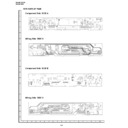
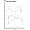
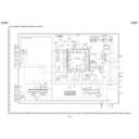
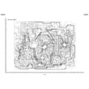
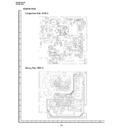
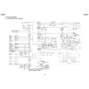
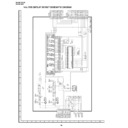
DV-NC60H (serv.man32)
DVD main PWB wiring side A
Service Manual
|
1
|
188.34 KB
|
|
|
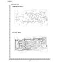
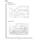
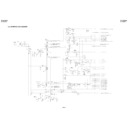
DV-NC60H (serv.man37)
AV PWB component wiring side A
Service Manual
|
1
|
93.83 KB
|
|
|
DV-NC60H (serv.man37)
AV PWB component wiring side A
Service Manual
|
1
|
93.83 KB
|
|
|
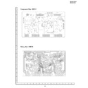
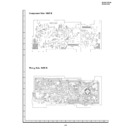
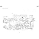
DV-NC60H (serv.man36)
DVD display PWB component wiring side A B
Service Manual
|
1
|
133.43 KB
|
|
|
DV-NC60H (serv.man36)
DVD display PWB component wiring side A B
Service Manual
|
1
|
133.43 KB
|
|
|
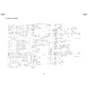
DV-NC60H (serv.man35)
VCR display PWB component wiring side A B
Service Manual
|
1
|
156.29 KB
|
|
|
DV-NC60H (serv.man35)
VCR display PWB component wiring side A B
Service Manual
|
1
|
156.29 KB
|
|
|
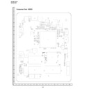
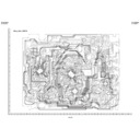
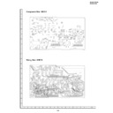
DV-NC60H (serv.man34)
DVD main PWB wiring side B
Service Manual
|
1
|
18.8 KB
|
|
|
DV-NC60H (serv.man34)
DVD main PWB wiring side B
Service Manual
|
1
|
18.8 KB
|
|
|
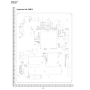
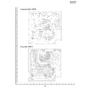
DV-NC60H (serv.man33)
DVD main PWB component side B
Service Manual
|
1
|
18.8 KB
|
|
|
DV-NC60H (serv.man33)
DVD main PWB component side B
Service Manual
|
1
|
18.8 KB
|
|
|
DV-NC60H (serv.man32)
DVD main PWB wiring side A
Service Manual
|
1
|
188.34 KB
|
|
|
DV-NC60H (serv.man38)
AV PWB component wiring side B
Service Manual
|
1
|
173.02 KB
|
|
|
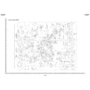
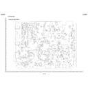
DV-NC60H (serv.man31)
DVD main PWB component side A
Service Manual
|
1
|
21.5 KB
|
|
|
DV-NC60H (serv.man31)
DVD main PWB component side A
Service Manual
|
1
|
21.5 KB
|
|
|
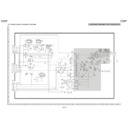
DV-NC60H (serv.man30)
VCR main circuit diagram 4
Service Manual
|
1
|
111.42 KB
|
|
|
DV-NC60H (serv.man30)
VCR main circuit diagram 4
Service Manual
|
1
|
111.42 KB
|
|
|
DV-NC60H (serv.man29)
VCR main circuit diagram 3
Service Manual
|
1
|
556.22 KB
|
|
|
DV-NC60H (serv.man29)
VCR main circuit diagram 3
Service Manual
|
1
|
556.22 KB
|
|
|
DV-NC60H (serv.man28)
VCR main circuit diagram 2
Service Manual
|
1
|
383.71 KB
|
|
|
DV-NC60H (serv.man28)
VCR main circuit diagram 2
Service Manual
|
1
|
383.71 KB
|
|
|
DV-NC60H (serv.man27)
VCR main circuit diagram 1
Service Manual
|
1
|
516.35 KB
|
|
|
DV-NC60H (serv.man27)
VCR main circuit diagram 1
Service Manual
|
1
|
516.35 KB
|
|
|
DV-NC60H (serv.man43)
Interface PWB component wiring side A
Service Manual
|
1
|
159.74 KB
|
|
|
DV-NC60H (serv.man48)
VCR main PWB wiring side B
Service Manual
|
2
|
529.79 KB
|
|
|
DV-NC60H (serv.man48)
VCR main PWB wiring side B
Service Manual
|
2
|
529.79 KB
|
|
|
DV-NC60H (serv.man47)
VCR main PWB component side B
Service Manual
|
1
|
360.95 KB
|
|
|
DV-NC60H (serv.man47)
VCR main PWB component side B
Service Manual
|
1
|
360.95 KB
|
|
|
DV-NC60H (serv.man46)
VCR main PWB wiring side A
Service Manual
|
1
|
514.42 KB
|
|
|
DV-NC60H (serv.man46)
VCR main PWB wiring side A
Service Manual
|
1
|
514.42 KB
|
|
|
DV-NC60H (serv.man45)
VCR main PWB component side A
Service Manual
|
1
|
342.35 KB
|
|
|
DV-NC60H (serv.man45)
VCR main PWB component side A
Service Manual
|
1
|
342.35 KB
|
|
|
DV-NC60H (serv.man44)
Interface PWB component wiring side B
Service Manual
|
1
|
173.5 KB
|
|
|
DV-NC60H (serv.man44)
Interface PWB component wiring side B
Service Manual
|
1
|
173.5 KB
|
|
|
DV-NC60H (serv.man26)
Power supply circuit diagrams
Service Manual
|
1
|
313.71 KB
|
|
|
DV-NC60H (serv.man43)
Interface PWB component wiring side A
Service Manual
|
1
|
159.74 KB
|
|
|
DV-NC60H (serv.man42)
Power PWB component wiring side B
Service Manual
|
1
|
152.85 KB
|
|
|
DV-NC60H (serv.man42)
Power PWB component wiring side B
Service Manual
|
1
|
152.85 KB
|
|
|
DV-NC60H (serv.man41)
Power PWB component wiring side A
Service Manual
|
1
|
152.63 KB
|
|
|
DV-NC60H (serv.man41)
Power PWB component wiring side A
Service Manual
|
1
|
152.63 KB
|
|
|
DV-NC60H (serv.man40)
Terminal PWB component wiring side B
Service Manual
|
1
|
173.79 KB
|
|
|
DV-NC60H (serv.man40)
Terminal PWB component wiring side B
Service Manual
|
1
|
173.79 KB
|
|
|
DV-NC60H (serv.man39)
Terminal PWB component wiring side A
Service Manual
|
1
|
105.01 KB
|
|
|
DV-NC60H (serv.man39)
Terminal PWB component wiring side A
Service Manual
|
1
|
105.01 KB
|
|
|
DV-NC60H (serv.man38)
AV PWB component wiring side B
Service Manual
|
1
|
173.02 KB
|
|
|
DV-NC60H (serv.man8)
Operation of pickup
Service Manual
|
1
|
68.48 KB
|
|
|
DV-NC60H (serv.man14)
System servo block diagram
Service Manual
|
1
|
333.19 KB
|
|
|
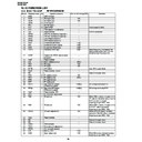
DV-NC60H (serv.man13)
Function list
Service Manual
|
24
|
212.45 KB
|
|
|
DV-NC60H (serv.man13)
Function list
Service Manual
|
24
|
212.45 KB
|
|
|
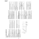
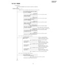
DV-NC60H (serv.man12)
Troubleshooting
Service Manual
|
14
|
151.56 KB
|
|
|
DV-NC60H (serv.man12)
Troubleshooting
Service Manual
|
14
|
151.56 KB
|
|
|
DV-NC60H (serv.man11)
Test mode
Service Manual
|
3
|
23.54 KB
|
|
|
DV-NC60H (serv.man11)
Test mode
Service Manual
|
3
|
23.54 KB
|
|
|
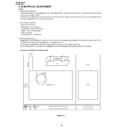
DV-NC60H (serv.man10)
Electrical adjustment
Service Manual
|
3
|
28.24 KB
|
|
|
DV-NC60H (serv.man10)
Electrical adjustment
Service Manual
|
3
|
28.24 KB
|
|
|
DV-NC60H (serv.man9)
Adjustment, replacement and assembly of mechanical units
Service Manual
|
23
|
692.66 KB
|
|
|
DV-NC60H (serv.man26)
Power supply circuit diagrams
Service Manual
|
1
|
313.71 KB
|
|
|
DV-NC60H (serv.man8)
Operation of pickup
Service Manual
|
1
|
68.48 KB
|
|
|
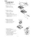
DV-NC60H (serv.man7)
Disassembly instructions
Service Manual
|
4
|
568.17 KB
|
|
|
DV-NC60H (serv.man7)
Disassembly instructions
Service Manual
|
4
|
568.17 KB
|
|
|
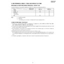
DV-NC60H (serv.man5)
Maintenance check items
Service Manual
|
1
|
9.13 KB
|
|
|
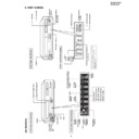
DV-NC60H (serv.man4)
Part names
Service Manual
|
4
|
180.66 KB
|
|
|
DV-NC60H (serv.man4)
Part names
Service Manual
|
4
|
180.66 KB
|
|
|
DV-NC60H (serv.man3)
Important servicing notes
Service Manual
|
1
|
97.5 KB
|
|
|
DV-NC60H (serv.man3)
Important servicing notes
Service Manual
|
1
|
97.5 KB
|
|
|
DV-NC60H (serv.man2)
Contents
Service Manual
|
1
|
52.62 KB
|
|
|
DV-NC60H (serv.man2)
Contents
Service Manual
|
1
|
52.62 KB
|
|
|
DV-NC60H (serv.man15)
Signal flow block diagram
Service Manual
|
1
|
269.41 KB
|
|
|
DV-NC60H (serv.man25)
Terminal circuit diagrams
Service Manual
|
1
|
293.32 KB
|
|
|
DV-NC60H (serv.man25)
Terminal circuit diagrams
Service Manual
|
1
|
293.32 KB
|
|
|
DV-NC60H (serv.man24)
AV circuit diagrams
Service Manual
|
1
|
313.56 KB
|
|
|
DV-NC60H (serv.man24)
AV circuit diagrams
Service Manual
|
1
|
313.56 KB
|
|
|
DV-NC60H (serv.man22)
DVD display circuit diagrams
Service Manual
|
1
|
159.71 KB
|
|
|
DV-NC60H (serv.man21)
DVD main circuit diagram 2
Service Manual
|
1
|
775.3 KB
|
|
|
DV-NC60H (serv.man21)
DVD main circuit diagram 2
Service Manual
|
1
|
775.3 KB
|
|
|
DV-NC60H (serv.man20)
DVD main circuit diagram 1
Service Manual
|
1
|
484.93 KB
|
|
|
DV-NC60H (serv.man20)
DVD main circuit diagram 1
Service Manual
|
1
|
484.93 KB
|
|
|
DV-NC60H (serv.man19)
VCR display circuit diagram
Service Manual
|
1
|
161.48 KB
|
|
|
DV-NC60H (serv.man19)
VCR display circuit diagram
Service Manual
|
1
|
161.48 KB
|
|
|
DV-NC60H (serv.man18)
Power block diagram
Service Manual
|
1
|
243.81 KB
|
|
|
DV-NC60H (serv.man18)
Power block diagram
Service Manual
|
1
|
243.81 KB
|
|
|
DV-NC60H (serv.man17)
Audio block diagram
Service Manual
|
1
|
258.91 KB
|
|
|
DV-NC60H (serv.man17)
Audio block diagram
Service Manual
|
1
|
258.91 KB
|
|
|
DV-NC60H (serv.man16)
Main block diagram
Service Manual
|
1
|
664.83 KB
|
|
|
DV-NC60H (serv.man16)
Main block diagram
Service Manual
|
1
|
664.83 KB
|
|
|
DV-NC60H (serv.man15)
Signal flow block diagram
Service Manual
|
1
|
269.41 KB
|
|
|
DV-NC60H (serv.man14)
System servo block diagram
Service Manual
|
1
|
333.19 KB
|
|
|
DV-NC60H (serv.man50)
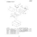
Packing of the set
Service Manual / Parts Guide
|
2
|
25.71 KB
|
|
|
DV-NC60H (serv.man49)
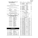
Parts listing and exploded views
Service Manual / Parts Guide
|
22
|
638.88 KB
|
|
|
DV-NC60H (serv.man49)
Parts listing and exploded views
Service Manual / Parts Guide
|
22
|
638.88 KB
|
|
|
DV-NC60H (serv.man50)
Packing of the set
Service Manual / Parts Guide
|
2
|
25.71 KB
|
|
|
DV-NC60H
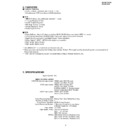
Features and
Service Manual / Specification
|
2
|
18.29 KB
|
|
|
DV-NC60H
Features and
Service Manual / Specification
|
2
|
18.29 KB
|
|
|
DV-NC60H (serv.man51)
No audio when playing back Phantom of the Opera disc
Service Manual / Technical Bulletin
|
1
|
4.63 KB
|
|
|
DV-NC60H (serv.man53)
PIN number and postcode reset procedure
Service Manual / Technical Bulletin
|
1
|
14.8 KB
|
|
|
DV-NC60H (serv.man53)
PIN number and postcode reset procedure
Service Manual / Technical Bulletin
|
1
|
14.8 KB
|
|
|
DV-NC60H (serv.man54)
EEPROM setting procedure is missing from the
Service Manual / Technical Bulletin
|
3
|
24.29 KB
|
|
|
DV-NC60H (serv.man54)
EEPROM setting procedure is missing from the
Service Manual / Technical Bulletin
|
3
|
24.29 KB
|

