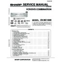
Sharp DV-NC100H Service Manual ▷ View online
1
DV-NC100H
S45T4DV-NC100
SERVICE MANUAL
In the interests of user-safety (Required by safety
regulations in some countries) the set should be
restored to its original condition and only parts
identical to those specified be used.
regulations in some countries) the set should be
restored to its original condition and only parts
identical to those specified be used.
MODEL
SERVICE MANUAL
VCR/DVD COMBINATION
MODEL
DV-NC100H
VCR/DVD COMBINATION
SHARP CORPORATION
DV-NC100H
MAIN SECTION
1. SPECIFICATIONS ................................................................................................................................................ 1-1-1
2. LASER BEAM SAFETY PRECAUTIONS ............................................................................................................. 1-2-1
3. IMPORTANT SAFEGUARDS AND PRECAUTIONS ............................................................................................ 1-3-1
4. STANDARD NOTES FOR SERVICING ................................................................................................................ 1-4-1
5. PREPARATION FOR SERVICING ....................................................................................................................... 1-5-1
6. OPERATING CONTROLS AND FUNCTIONS ...................................................................................................... 1-6-1
7. CABINET DISASSEMBLY INSTRUCTIONS ........................................................................................................ 1-7-1
8. ELECTRICAL ADJUSTMENT INSTRUCTIONS ................................................................................................... 1-8-1
9. FIRMWARE RENEWAL MODE ............................................................................................................................ 1-9-1
10. TROUBLESHOOTING ........................................................................................................................................ 1-10-1
11. BLOCK DIAGRAMS ............................................................................................................................................ 1-11-1
12. FUNCTION INDICATOR SYMBOLS ................................................................................................................... 1-11-9
13. SCHEMATIC DIAGRAMS/ CBA’S AND TEST POINTS ..................................................................................... 1-12-1
14. WAVEFORMS ..................................................................................................................................................... 1-13-1
15. WIRING DIAGRAM ............................................................................................................................................. 1-14-1
16. IC PIN FUNCTION DESCRIPTIONS .................................................................................................................. 1-15-1
17. LEAD IDENTIFICATIONS ................................................................................................................................... 1-16-1
18. EXPLODED VIEWS ............................................................................................................................................ 1-17-1
19. MECHANICAL PARTS LIST ............................................................................................................................... 1-18-1
20. ELECTRICAL PARTS LIST ................................................................................................................................ 1-19-1
DECK MECHANISM SECTION
1. STANDARD MAINTENANCE ............................................................................................................................... 2-1-1
2. SERVICE FIXTURE AND TOOLS ........................................................................................................................ 2-2-1
3. MECHANICAL ALIGNMENT PROCEDURES ...................................................................................................... 2-3-1
4. DISASSEMBLY / ASSEMBLY PROCEDURES OF DECK MECHANISM ............................................................ 2-4-1
5. ALIGNMENT PROCEDURES OF MECHANISM .................................................................................................. 2-5-1
6. DECK EXPLODED VIEWS ................................................................................................................................... 2-6-1
7. DECK PARTS LIST ............................................................................................................................................... 2-7-1
CONTENTS
VIDEO Plus+ and PlusCode are registered
trademarks of Gemstar Development Corporation.
The VIDEO Plus+ system is manufactured under
license from Gemstar Development Corporation.
trademarks of Gemstar Development Corporation.
The VIDEO Plus+ system is manufactured under
license from Gemstar Development Corporation.
2
PULL OPEN
DV- N C 1 0 0
OPERATE
OPEN/CLOSE
PLAY
STOP
DVD
VCR
TIMER
REC
PLAY
REW
STOP/
EJECT
EJECT
(TRACKING)
OUTPUT
The region number for this
VCR/DVD is 2.
VCR/DVD is 2.
FF
CH
MAIN SECTION
VCR/DVD COMBINATION
DV-NC100H
TABLE OF CONTENTS
1. SPECIFICATIONS .......................................................................................... 1-1-1
2. LASER BEAM SAFETY PRECAUTIONS ....................................................... 1-2-1
3. IMPORTANT SAFEGUARDS AND PRECAUTIONS ...................................... 1-3-1
4. STANDARD NOTES FOR SERVICING .......................................................... 1-4-1
5. PREPARATION FOR SERVICING ................................................................. 1-5-1
6. OPERATING CONTROLS AND FUNCTIONS ................................................ 1-6-1
7. CABINET DISASSEMBLY INSTRUCTIONS .................................................. 1-7-1
8. ELECTRICAL ADJUSTMENT INSTRUCTIONS ............................................. 1-8-1
9. FIRMWARE RENEWAL MODE ...................................................................... 1-9-1
10. TROUBLESHOOTING .................................................................................. 1-10-1
11. BLOCK DIAGRAMS ...................................................................................... 1-11-1
12. FUNCTION INDICATOR SYMBOLS ............................................................. 1-11-9
13. SCHEMATIC DIAGRAMS/ CBA’S AND TEST POINTS ............................... 1-12-1
14. WAVEFORMS ............................................................................................... 1-13-1
15. WIRING DIAGRAM ....................................................................................... 1-14-1
16. IC PIN FUNCTION DESCRIPTIONS ............................................................ 1-15-1
17. LEAD IDENTIFICATIONS ............................................................................. 1-16-1
18. EXPLODED VIEWS ...................................................................................... 1-17-1
19. MECHANICAL PARTS LIST ......................................................................... 1-18-1
20. ELECTRICAL PARTS LIST ........................................................................... 1-19-1
1-1-1
H9741SP
SPECIFICATIONS
Description
Unit
Minimum
Nominal
Maximum
Remark
1. Video
1-1. Video Output (PB)
Vp-p
0.8
1
1.2
9HSFL6A
9HSFL6M
W/O Burst
9HSFL6A
9HSFL6K
9HSFL6HA
1-2. Video Output (R/P)
Vp-p
0.8
1
1.2
1-3. Video S/N Y (R/P)
dB
40
43
1-4. Video Color S/N AM (R/P)
dB
35
41
1-5. Video Color S/N PM (R/P)
dB
33
38
1-6. Resolution (PB)
Line
210
230
2. Servo
2-1. Jitter Low
µ
sec
0.07
0.12
2-2. Wow & Flutter
%
0.3
0.6
3. Normal Audio
3-1. Output (PB)
dBV
-9
-4
-2
3-2. Output (R/P)
dBV
-9
-4
-1
3-3. S/N (R/P)
dB
36
40
3-4. Distortion (R/P)
%
1.5
4
3-5. Freq. resp (R/P) at 200Hz (PB)
dB
-6
-3
(-20dB ref. 1kHz) at 8kHz (PB)
dB
-6
-3
5
5
4. Tuner
4-1. Video output
Vp-p
0.8
1
1.2
4-2. Video S/N
dB
40
45
4-3. Audio output
dB
-10
-6
-2
4-4. Audio S/N
dB
40
50
5. Hi-Fi Audio
5-1. Output (PB)
dBV
-12
-9
-6
5-2. Dynamic Range
dB
70
80
5-3. Freq. resp (6dB B.W)
Hz
20 ~ 20K
< VCR Section >
TAPE SPEED: SP
Notes:
1. Nominal specs represent the design specs. All units should be able to approximate these – some will exceed and
1. Nominal specs represent the design specs. All units should be able to approximate these – some will exceed and
some may drop slightly below these specs. Limit specs represent the absolute worst condition that still might be
considered acceptable; In no case should a unit fail to meet limit specs.
considered acceptable; In no case should a unit fail to meet limit specs.
2. For test tapes, refer to "SERVICE FIXTURE AND TOOLS" section.
1-1-2
H9741SP
NOTES:
1. All Items are measured without pre-emphasis unless otherwise specified.
2. Power supply : AC220 - 240 V ~ 50 Hz
3. Load imp. : 100 k ohm
4. Room ambient : 5
°
C ~ 40
°
C
5. Power consumption: 30 W (Standby: 5.5 W)
6. Weight: 6.84 lbs (3.2kg)
7. Dimension: 435 mm X 94 mm X 233 mm
ITEM
CONDITIONS
UNIT
NOMINAL
LIMIT
1 Video Output
75
Ω
Vpp
1.0
±
0.1
2 Coaxial Digital Out
mVpp
500
3 Audio (PCM)
3-1. Output Level
1 kHz 0 dB
Vrm
2.0
3-2. S/N
dB
110
3-3. Freq. Response
DVD
fs=48 kHz 20 ~ 22 kHz
dB
±
1.5
CD
fs=44.1 kHz 20 ~ 22 kHz
dB
±
1.5
3-4. THD +N
DVD
1k Hz 0 dB
%
0.01
CD
1k Hz 0 dB
%
0.01
< DVD Section >

