Sharp DV-L88 (serv.man8) Service Manual ▷ View online
DV-L88S/S(H)
DV-L88W/W(A)
DV-L88W/W(A)
20
8.
TR
OUBLESHOO
TING
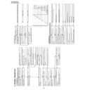
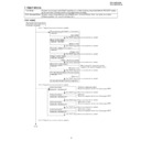
Check AC adapter or battery-pack.
No
Voltage on DC JACK (Approx. 10V) or battery
terminal (8.4 - 6V)?
Yes
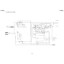
The power cannot be turned on.(1)
•When using the AC adapter ------check circuit
around F901, Q904, Q905.
•When using battery------check circuit around
F902, Q906, Q913.
No
Voltage specified above (Approx.6 - 10V) on
TP9002, TP9003?
Yes
Voltage of approx. 6 - 11V supplied on 4 pin of
IC5503?
No
Voltage of approx. 5V supplied on 72 pin of
IC5502 (TV microcomputer)?
Yes
Yes
29 pin of IC5502 still “L”?
No
Oscillation signal of 32kHz checked on 23, 24 pins
of IC5502?
Yes
Check the IC5502 and X5502.
Check the Q5503 and Q5504.
No
No
No
Yes
Circuit protector CP9001 is actuated (disconnection)
replace. Check LCD inverter circuit, INV-V line,
D5510, D5512, Q5506 and Q5507.
Refer to “
The key operation is disabled.
” or
“No operation is possible from the infrared remote
control.”.
No
•Approx. 5V outputted to 45 pin of IC5502?
•Approx. 5V outputted to 46 pin of IC5502?
(DVD mode)
No
Yes
Check PCON-H line between IC5502 - IC9001.
•Approx. 4.5 V supplied to 20 - 21 pins of IC9001?
•Approx. 4.5 V supplied to 22 pin of IC9001?
(DVD Mode)
Yes
Appropriate voltage outputted on each B line
(TP9005 - 9012)?
No
No
Yes
Triangle oscillation of approx. 0.6V p-p checked on
17 pin of IC9001?
Circuit protector CP9002 cut?
Yes
Check short circuit of each SWITCHING TR and
each B line.
* All the B lines cannot be outputted for short
circuit of even 1postion (1 line).
Replace IC5503.
Replace IC9001.
FLOW CHART NO.1
Attach junction line properly or replace junction line.
No
Wire between operation PWB and Power PWB
connected properly?
Yes
Yes
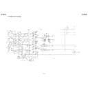
The key operation is disabled.
No
Slide switch does not function.
No
When slide switch is placed "ON", 5 pin of IC5502
is "L"?
Yes
Is the control voltage normally into the pins(78)
and (80) of IC5502? (78pin
→
KEY)
Replace S5501.
Yes
Replace operation pwb or S4001~S4005.
Replace IC5502.
No
Replace IC5502.
FLOW CHART NO.2
Check TVMI_5V line.
Replace the remote control receiver.
FLOW CHART NO.3
Operation is possible from the body, but no
operation is possible from the infrared remote
control.
Replace the remote control receiver or replace the
remote control transmitter is necessary.
Is 5V voltage supplied to the pin 2 terminal of
remote control receiver?
Is the "L" pulse sent out pin 3 terminal of receiver
when the infrared remote control is activated?
(Actuated with power button)
DVD cannot be operated but TV can be operated.
(DVD is actuated with play, stop button.)
To 2
1“L” pulse signal is generated from 79 pin of
IC5502?
(Actuated with power button)
No
No
No
Yes
No
To 1
Replace IC5502.
No
Yes
Check line of 2 pin of IC4001.
2“L” pulse signal is generated from 32 pin of
IC502?
(DVD is actuated with play, stop button.)
Replace IC502.
No
Yes
Check D512 line.
Yes
Yes
Yes
No operation is possible from the infrared remote control.
0.5
1
1.5
2
2.5
3
3.5
4
4.5
5
PLAY
STOP
STILL
SKIP/BACK
SKIP/FORWARD
DVD/INPUT
SETUP/ADJ
UP
RIGHT
LEFT
DOWN
ENTER
RETURN
VOL-UP
VOL-DOWN
DV-L88S/S(H)
DV-L88W/W(A)
DV-L88W/W(A)
21
FLOW CHART NO.4
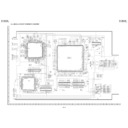
Is the tray lid open?
When S802 is pressed, are the pins 3 and 4
short-circuited?
Check the connection between pins 2 or 4 of S802
and pin 27 of IC502.
Does the pickup move in the direction of inner
periphery?
No
No
No
No
Check the cable connecting to the CN7302.
(Check the CN7302 and line of pins 2 and 4 of IC705.)
Check the cable connecting to the CN7303.
Replace the S802.
Yes
No
Yes
After moving in the direction of inner periphery,
does the pickup move in the direction of outer
periphery?
Yes
Check the M_4.8V line.
Is 4.8V being applied to the pins 16 and 17 of
IC7701?
Yes
Replace the IC7701.
Yes
The disc does not rotate.
No
Is FE signal inputted into the pin 150 of IC701.
Check or replace IC701.
Check the line between the IC301 and IC701.
FLOW CHART NO.5
When removing disc and applying load to spin
motor (by stopping with hand, etc.), objective lends
moves up and down? (Checking item to symptom)
Note) If load is not applied to spin, lens does not
move and becomes NO DISC immediately.
See FLOW CHART NO.6<The [No Disc] indication.
(In case focus servo does not function.)>
Replace IC301.
Is there input signal on the pins(50,55) and (49,54)
of IC301?
Is FE signal output to the pin 21 of IC301 when
the disc is set?
No
No
Check the connection of optical pickup cable.
If it is normal, replace the optical pickup.
Yes
No
Yes
Yes
Yes
The [No Disc] indication.
(In case of f
ocus error)
In case of CD For DVD, 58, 59, 63, and 64
FLOW CHART NO.6
Is the focus control signal output to the pin 14 of
IC701?
Check the IC701 DAC power source periphery
circuit. If it is normal, replace IC701.
Check M_5V line.
Is 8V voltage applied to the pins 8 and 27 and
25 and 24 of IC705?
Replace IC705.
Is the focus control signal from the pin 158 of
IC701 input into the pin 20 of IC705?
Check the focus control signal (DA0) line between
the IC705 and IC701.
Is the focus control drive voltage output from the
pins 29 and 30 of IC705?
No
No
No
Yes
Yes
Yes
No
Yes
The [No Disc] indication.
(In case f
ocus ser
v
o
does not function.)
Check the line between the IC705 and the focus
actuator.
Focus control drive voltage applied to 27, 29 pin
of CN7301 (focus actuator terminal)?
Check the connection of optical pickup cable.
If it is normal, replace the optical pickup.
FLOW CHART NO.7
Check the D_3.1V line and A_5V line.
Is the drive signal (SEL) of Q301 (LD POWER
ON) being output to the pin 37 of IC701?
Is the drive signal (LDO1) of Q302 (LD POWER
CTL) being output to the pin 45 of IC301?
When S801 is pressed, is the base of Q303 0.8V?
Is the voltage of 3.3V being applied to the emitter
of Q301? And, is the voltage of 3.4V being applied
to the emitter of Q302?
Is the voltage of 3.1V and 2.3V being applied to
the pins 14 and 23 of CN7301, respectively?
Check the connection of optical pickup cable.
If it is normal, replace the pickup.
Check the Q301 and line between Q302 and
CN301.
Check the line from the pin 37 of IC701 to the base
of Q301.
Check the line between the pin 45 of IC301 and
base of Q302.
Check the line between S801 and R323.
No
No
No
No
No
No
Yes
Yes
Yes
Yes
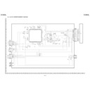
The DVD disc is not recognized.
(When the laser beam does not go on)
FLOW CHART NO.8
Check the A_5V line.
Is the drive signal (LDO2) of Q304 (LD POWER
CTL) being output to the pin 4 of IC301?
When S801 is pressed, is the base of Q304 0.8V?
Is the voltage of 3.4V being applied to the emitter
of Q303?
Is the voltage of 2.3V being applied to the pin 9
of CN7301?
Check the connection of optical pickup cable.
If it is normal, replace the pickup
Check the line between Q304 and CN7301.
Check the line between the pin 4 of IC301 and
base of Q303.
Check the line between S801 and R323.
No
No
No
No
Yes
Yes
Yes
The CD disc is not recognized.
(When the laser beam does not go on)
FLOW CHART NO.9
Check tray switch. S801, 802
No
Check for contamination of objective lens of
optical pickup.
Replace the optical pickup unit.
When cover is closed, disc starts rotating?
Check the main PWB unit.
Set disc to mechanism.
Replace the main PWB unit.
Is the level of RF signal which is output from
pin 28 of IC301, normal?
No
No
No
Yes
Yes
Yes
Yes
Both picture and sound do not oper
ate nor
mally
.(1)
DV-L88S/S(H)
DV-L88W/W(A)
DV-L88W/W(A)
22
FLOW CHART NO.10
Check or replace Q2201.
Set the disc on the disc tray.
Check the V-MUTE line.(Pin3 of D2204)
5V applied to 1 pin of IC2201?
Are the video signals shown above input into
the pins of IC2201?
IC2201 2PIN Y/CR
IC2201 15PIN C/CB
Are the video signal outputted to each pins of
IC2201?
(1)When S1-OUT/VIDEO OUT is selected with the
signal selection switch(Q2201).
IC2201 11PIN CVBS
IC2201 6PIN S-Y
IC2201 12PIN S-C
Check the line between the pins of main unit
IC601 and the pins of IC2201.
IC601 105PIN
→
IC2201 2PIN Y/CR
IC601 106PIN
→
IC2201 15PIN C/CB
No
No
No
Yes
No
Yes
Yes
Picture do not oper
ate nor
mally
.
FLOW CHART NO.11
Check or replace IC6801.
Set disc to DISC tray and play.
Digital sound signal inputted to each pin of
IC6801?
IC6801 5PIN AMCLK
IC6801 3PIN ABCLK
IC6801 1PIN ALRCLK
IC6801 2PIN AOUT0
Check each line between each pin of IC601 and
each input pin of IC6801.
IC601 131PIN
→
IC6801 5PIN AMCLK
IC601 141PIN
→
IC6801 3PIN ABCLK
IC601 139PIN
→
IC6801 1PIN ALRCLK
IC601 136PIN
→
IC6801 2PIN AOUT0
System control signal inputted to each pin of
IC6801?
IC6801 26PIN DAC DA
IC6801 27PIN DAC CK
IC6801 28PIN DAC L
IC6801 22PIN RSTO I
Check or replace IC6801.
Check each line between each pin of IC504 and
IC251 and each input pin of IC6801.
IC504 110PIN
→
IC6801 26PIN DAC DA
IC504 111PIN
→
IC6801 27PIN DAC CK
IC504 112PIN
→
IC6801 28PIN DAC L
IC251 77PIN
→
IC6801 22PIN RSTO I
No
No
Yes
Yes
Yes
Check or replace IC6610.
Yes
Yes
Sound is not given properly from speaker.
Control signal inputted to each in of IC6610?
IC6610 2PIN VOL_UP
IC6610 3PIN VOL_DOWN
Check from each pin of IC5502 to each input pin
of IC6610.
IC5502 33PIN
→
IC6610 2PIN VOL_UP
IC5502 4PIN
→
IC6610 3PIN VOL_DOWN
No
Yes
Is 15 pin of IC6610 low?
Check the Q6609, D6601, R6001, J6001.
No
Yes
Sound signal inputted to each pin of IC6610?
IC6610 5PIN Lch Input
IC6610 23PIN Rch Input
Check the IC6604, IC6605 and IC6607 and
peripheral circuit.
No
Yes
Charge troubleshooting
Go to item 4.
Charge LED (orange) lights on?
1.
Yes
No
No
No
Yes
No
No
Yes
Yes
Yes
No
Power supplied from AC adapter?
Power of main unit can be turned on and off?
Power of main unit OFF?
F901 fuse is not cut?
Voltage of battery alone is 2V or more?
Replace fuse.
Failure of battery.
Cannot be charge.
Failure other than charging.
Cannot be charged when power is ON.
Turn off power and check.
Breakdown of IC5502.
44 pin of IC5502 is H?
4.
No
No
No
No
Yes
Yes
Yes
2 pin of IC901 oscillating at approx. 200kHz?
19 pin of IC901 oscillating at approx. 200kHz?
Voltage on C901?
Yes
Yes
Investigate CHG_ON line.
Investigate from C901 to battery terminal.
Check around IC901 or breakdown of IC901.
Check around IC901 or breakdown of IC901.
Investigate Q908, D906, L901, and R915.
In the condition that power is supplied from AC adapter and power is off, nothing is connected to battery terminal.
2.
Yes
No
Yes
No
Yes
No
Voltage of 0V/8.4V generated to battery terminal
cyclically.
"H" voltage on 8 pin of IC5502?
Yes
Investigate CHG_ON line. Charging circuit must
function accompanied by CHG_ON cyclically.
Voltage on 77 pin of IC5502?
44 pin of IC5502 repeating H/L cyclically?
If certain voltage is on, investigate BAT_V line.
When battery is not connected, voltage of 0V/4.2V
is outputted cyclically.
Study on other items.
Investigate line of DCIN_H.
Only battery is connected. (Assume herein that battery with voltage of 7.4 V is connected.)
3.
Yes
No
No
No
Yes
Voltage of 3.7V on 77 pin of IC5502?
Voltage on 6 pin of Q905?
Yes
1V or less on 4 pin of D5509?
Investigate around Q905.
No problems with this item.
Investigate around IC5505.
Investigate around IC5505.
DV-L88S/S(H)
DV-L88W/W(A)
DV-L88W/W(A)
23
- M E M O -
Display

