Sharp DV-L70 (serv.man4) Service Manual ▷ View online
13
DV-L70S
DV-L70BL
DV-L70W
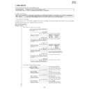
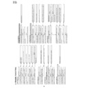
7. TEST MODE
Adjustment Mode
A power source is put with pushing and .
ROM renewal mode
It is put with pushing a playback key and a still key.
When a power source is put with pushing a key.
When there is a disc Error rate display mode (There are a DVD and CD mode of it, and a disc is put, and a key manipulates.)
When there is
When there is
Test mode (Version display mode, color bar pattern display mode, mecha test mode.)
A power source is put.
[The flow of the test mode]
A power source is put, and closing, a playback key and a stop key are pushed for about two seconds at the same time
without a disk the disk cover. It goes into the (test mode.
The preparation date display of the program
10000000
∗∗∗∗∗∗∗∗
(Last updata)
Model number display
10000001
∗∗∗∗∗∗∗∗
(Model number)
The preparation date display of the program
10000002
∗∗∗∗∗∗∗∗
(Program ver.)
Region code display
10000003
∗∗∗∗∗∗∗∗
(Region code)
Color bar display
20000001 00000000
Microcord version display
10000004
∗∗∗∗∗∗∗∗
(Microcode ver.)
The preparation date display of the servo program
10000005
∗∗∗∗∗∗∗∗
(Servo ver.)
It is returned to the test mode initial image plane.
<The "2" key of the remote controller is pushed.>
<The "1" key of the remote controller is pushed.>
Test mode initial image plane
F0000000 00000000
The "playback" key of the remote controller is pushed.
The "playback" key of the remote controller is pushed.
The "playback" key of the remote controller is pushed.
The "reactivation" key of the remote controller is pushed.
The "playback" key of the remote controller is pushed.
The "playback" key of the remote controller is pushed.
The "playback" key of the remote controller is pushed.
There is no copy guard signal.
As for the symptom when it was
dubbed in the video tape recorder?
As for the symptom when it was
dubbed in the video tape recorder?
Color bar display
20000002 00000000
The "playback" key of the remote controller is pushed.
AGC only
As for the symptom when it was
dubbed in the video tape recorder?
As for the symptom when it was
dubbed in the video tape recorder?
Color bar display
20000003 00000000
The "playback" key of the remote controller is pushed.
AGC+Color stripe1
As for the symptom when it was
dubbed in the video tape recorder?
As for the symptom when it was
dubbed in the video tape recorder?
AGC+Color stripe2
As for the symptom when it was
dubbed in the video tape recorder?
As for the symptom when it was
dubbed in the video tape recorder?
Color bar display
20000003 00000000
To (1)
Model name Model number
DVL70S
DVL70S
00000702
DV-L70BL
00000702
DV-L70W
00000703
Region No.
Region cord
4
00000008
3
00000004
2
00000002
Micro-code is the thing of the process
program of the system integrated circuit.
program of the system integrated circuit.
DV-L70S
DV-L70BL
DV-L70W
14
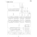
Mecah test mode display
3000E000 EEEEEEEE
<Disk is put, and the "2" key of the remote controller is pushed.>
*It is usually returned in power source off for the state.
<The "3" key of the remote controller is pushed.>
<The "1" key of the remote controller is pushed.>
When it failed in servo initialization.
It is returned to the test mode initial image plane
by pushing "the playback" of the remote
controller and a "stop" key at the same time.
It is returned to the test mode initial image plane
by pushing "the playback" of the remote
controller and a "stop" key at the same time.
Laser test mode display
0D000100 00000000
The "playback" key of the remote controller is pushed.
A playback key and a stop key are pushed at
the same time, and it is returned to the test mode
initial image plane.
the same time, and it is returned to the test mode
initial image plane.
DVD mode (Light is sent out by DVD laser,
and a pickup is moved to the circumference.)
DD000100 00000000
The "playback" key of the remote controller is pushed.
CD mode (Light is sent out by CD laser,
and a pickup is moved to the circumference.)
CD000100 00000000
The "playback" key of the remote controller is pushed.
The emission of the laser can be confirmed when
a disk cover is opened and a cap switch is
pushed with the thin bar and so on.
Note:Not to face the light of the laser squarely,
caution!
a disk cover is opened and a cap switch is
pushed with the thin bar and so on.
Note:Not to face the light of the laser squarely,
caution!
Slead motor is rotated, and it moves a pickup to
the circumference.
the circumference.
Laser off mode (Light isn't sent out by laser,
and a pickup is moved to the circumference.)
FD000100 00000000
The "playback" key of the remote controller is pushed.
The "playback" key of the remote controller is pushed.
The "playback" key of the remote controller is pushed.
It is returned to the cause in power source off.
How to distinguish a difference in the DVD laser
and the CD laser.
DVD laser is lighter in comparison with the CD laser.
Note:Not to face the light of the laser squarely,
caution!
How to distinguish a difference in the DVD laser
and the CD laser.
DVD laser is lighter in comparison with the CD laser.
Note:Not to face the light of the laser squarely,
caution!
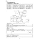
From (1)
To (2)
Mecah test mode display
30000000 00000000
DDT mode
0D000100 00000000
DDT step 1
DD000201
∗∗
++--00
DDT mode
0D00E201 000000EE
When a disk is not in.
It is executed to focus on of DDT.
Focus offset value(
Focus offset value(
∗∗
)
Track offset value(++)
0 layer focus balance value(--)
0 layer focus balance value(--)
The "playback" key of the remote controller is pushed.
DDT step 2
DD000202
∗∗
++0000
A track, slead on are done after RF gain outline adjustment and track balance adjustment are done.
0 layer RF gain value(
0 layer RF gain value(
∗∗
)
Track balance value(++)
0 layer focus balance value
0 layer focus balance value
The "playback" key of the remote controller is pushed.
DDT step 3
DD000203
∗∗
++0000
Just focus adjustment is done.
RF gain adjustment is done again after the completion.
0 layer focus balance value(
RF gain adjustment is done again after the completion.
0 layer focus balance value(
∗∗
)
Track RF gain value(++)
The "playback" key of the remote controller is pushed.
DDT step 4
DD000204
∗∗
000000
Focus gain adjustment is done.
0 layer focus gain value(
0 layer focus gain value(
∗∗
)
The "playback" key of the remote controller is pushed.
DDT step 5
DD000205
∗∗
000000
Track gain adjustment is done.
Track gain value(
Track gain value(
∗∗
)
DDT step 6
DD000206
∗∗
++0000 (DVD)
DD000206 00000000 (CD)
A two-layer disk does just focus of layer 1 and focus gain adjustment.
A CD does reading of TOC.
1 layer focus gain value(
A CD does reading of TOC.
1 layer focus gain value(
∗∗
)
1 layer focus balance value(++)
15
DV-L70S
DV-L70BL
DV-L70W
The "playback" key of the remote controller is pushed.
The "playback" key of the remote controller is pushed.
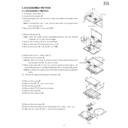
From (2)
Servo version display
F1000001 99071400
Focus offset value display
F1000002
∗∗∗∗∗∗∗∗
The "playback" key of the remote controller is pushed.
Track offset value display
F1000003
∗∗∗∗∗∗∗∗
The "playback" key of the remote controller is pushed.
0 layer focus balance value display
F1000004
∗∗∗∗∗∗∗∗
The "playback" key of the remote controller is pushed.
1 layer focus balance value display
F1000005
∗∗∗∗∗∗∗∗
The "playback" key of the remote controller is pushed.
Track balance value display
F1000006
∗∗∗∗∗∗∗∗
The "playback" key of the remote controller is pushed.
0 layer focus gain value display
F1000007
∗∗∗∗∗∗∗∗
The "playback" key of the remote controller is pushed.
1 layer focus gain value display
F1000008
∗∗∗∗∗∗∗∗
The "playback" key of the remote controller is pushed.
Track gaine value display
F1000009
∗∗∗∗∗∗∗∗
The "playback" key of the remote controller is pushed.
RF swing value display
F100000A
∗∗∗∗∗∗∗∗
The "playback" key of the remote controller is pushed.
RF gain value display
F100000B
∗∗∗∗∗∗∗∗
The "playback" key of the remote controller is pushed.
The "playback" key of the remote controller is pushed.
The inside switch ID value display
F100000C
∗∗∗∗∗∗∗∗
Display

