Sharp DV-L70 (serv.man24) Service Manual ▷ View online
DV-L70S
DV-L70BL
DV-L70W
8
Parts Code
Price Code
Remarks
Parts Code
Price Code
Remarks
QCNW-8145GEZZ
AQ
P.U. extension, 30-pin
QCNW-8151GEZZ
AQ
Inverter extension, 6-pin
QCNW-8146GEZZ
AQ
Spindle extension, 13-pin
QCNW-8152GEZZ
AQ
LCD panel extension, 32-pin
QCNW-8147GEZZ
AN
Sled extension, 2-pin
QCNW-8154GEZZ
AQ
Operation PWB extension, 12-pin
QCNW-8148GEZZ
AM
Power supply extension, 14-pin QCNW-1766TAZZ
BF
Inverter junction PWB
QCNW-8149GEZZ
AQ
Main LCD extension, 14-pin
QPWBF5002GEZZ
BF
LCD junction PWB
QCNW-8150GEZZ
AQ
Main LCD extension, 14-pin
QPWBF5003GEZZ
BF
Pickup junction PWB
Adjustment VR
R1102
Adjustment Point
Put a voltmeter between 6PIN (+7.5V) and 4PIN (GND) of TP1191.
Input Signal/Setting
No input
Adjustment Method
Adjust it to 7.50
±
0.02V.
Adjustment VR
R1103
Adjustment Point
Visual observation of the panel
Input Signal/Setting
Monoscope full screen
Adjustment Method
Adjust the screen so that it is located in the center.
Adjustment VR
R1104
Adjustment Point
Observe the 3PIN of TP1191 with a frequency counter.
Input Signal/Setting
No input, external input mode
Adjustment Method
Adjust it so as to get the HSY frequency of 15.625
±
0.01KHz
(64.0
µ
S).
HSY
15.625KHz
(64.0
µ
S)
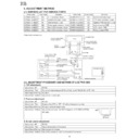
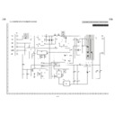
6-2. ADJUSTMENT PROCEDURE AND METHOD OF LCD PWB SIDE
1. 7.5V adjustment
2. Free run adjustment
3. Screen center adjustment
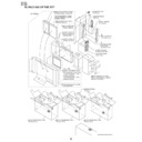
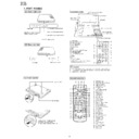
Drawing for service jigs
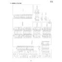
Operation cabinet
Mechanism
Power
supply PWB
supply PWB
PA
AE
AD
AC
AA
CN302
CN301
AB
MA
FFC
FFC spindle
Lead wire
FFC
Pickup junction PWB
QPWBF5003GEZZ
QPWBF5003GEZZ
Pickup
QCNW-8145GEZZ
QCNW-8145GEZZ
QCNW-8146GEZZ
QCNW-8147GEZZ
Sled
Sled
Power supply, 14-pole
QCNW-8148GEZZ
QCNW-8148GEZZ
QCNW-8154GEZZ
QCNW-8150GEZZ
LCD junction
QCNW-8152GEZZ
QCNW-8152GEZZ
LCD junction PWB
QPWBF5002GEZZ
QPWBF5002GEZZ
Inverter junction PWB
QCNW-1766TAZZ
QCNW-1766TAZZ
Inverter
QCNW-8151GEZZ
QCNW-8151GEZZ
Inverter PWB
QCNW-8149GEZZ
Lead wire
LC
LB
LA
LCD
LCD PWB
F
F
C
F
F
C
Panel
Main PWB
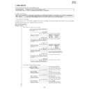
6. ADJUSTMENT METHOD
6-1. HARNESS LIST FOR SERVICE PARTS
9
DV-L70S
DV-L70BL
DV-L70W
Adjustment Point
Put voltmeters in 4PIN (GND), 5PIN (-16V) and 7PIN (13V) of TP1191.
Input Signal/Setting
Check in the DVD mode.
Adjustment Method
Check that each voltage indicates -16
±
1V and 13
±
0.5V respectively.
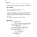
6-3. CHECK ITEMS OF LCD PWB SIDE
1. Power supply voltage check
Adjustment Point
Check the panel visually by connecting to the checker.
Input Signal/Setting
External input
Adjustment Method
Check that the horizontal movement of ODS is 1 mm or less when
inputting a signal in the external input mode with no signal input.
2. Free run check
Input
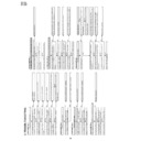
6-4. ADJUSTMENT PROCEDURE AND METHOD OF MAIN PWB SIDE
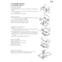
1. Press the UP+DOWN key is pushed at the same time, and made power source on.
2. It moves to the special mode(SP MODE), and a BACKLIGHT(HI/LOW/OFF) key is pushed and turned off.
3. After setting is completed, a power source is turned off.
4. Again, a UP+DOWN key is pushed at the same time, and a power source is turned on and made special mode.
5. An INPUT/ DVD key is pushed, and it becomes adjustment mode.
6. Each operation in the adjustment mode changes as follows:
(1) Switch the adjustment block with the TILT key input.
(2) Perform paging of each adjustment block with the RETARN key.
(3) Switch each adjustment item with the menu key input.
(4) Change each adjustment value with the left or right cursor key.
DAC adjustment
OPT adjustment
BAT adjustment
TV1
TV2
TV3
GAM0
TV1 adjustment
TV2 adjustment
TV3 adjustment
SBRI
GPOS
CONT
WB-R
WB-B
SCOL
STIN
COM
OSDH
BBRI
GAM2
DV-L70S
DV-L70BL
DV-L70W
10
1. DAC adjustment
(1) TV1 adjustment
(1) TV1 adjustment
Adjustment VR
GAM0
Initial value "44" adjustment is unnecessary.
Adjustment VR
SBRI
Adjustment Point
————
Input Signal/Setting
It is set in "56".
Adjustment VR
GPOS
Adjustment Point
Connect the oscilloscope to COM output (6PIN of TP1901) and GND.
Input Signal/Setting
Black-and-white 10STEP
Adjustment Method
Adjust the common amplitude to 8.0
±
0.1Vp-p.
8.0
±
0.1Vp-p
Adjustment VR
WB-R
Adjustment Point
Connect the oscilloscope to 3PIN (VG) and 4PIN (VR) of TP1901.
Input Signal/Setting
Black-and-white 10STEP
Adjustment Method
Adjust the white balance (red) so that peak-peak the equal of green and red output become equal.
(2) TV2 adjustment
Adjustment VR
WB-B
Adjustment Point
Dual the oscilloscope to 3PIN (VG) and 5PIN (VB) and GND of TP1901.
Input Signal/Setting
Black-and-white 10STEP
Adjustment Method
Adjust the white balance (blue) so that peak-peak the equal of green and blue output become equal.
Adjustment VR
SCOL
Adjustment Point
Connect the oscilloscope to 5PIN (VB) and GND of TP1901.
Input Signal/Setting
100% color bar
Adjustment Method
Adjust the blue amplitude of the color bar (black level to peak level) to 3.8
±
0.1Vpp.
Adjustment VR
GAM2
Adjustment Point
Connect the oscilloscope to 3PIN (VG) and GND of TP1901.
Input Signal/Setting
Black-and-white 10STEP
Adjustment Method
Adjust the Vpp of VG to 4.3
±
0.1Vp-p.
4.3
±
0.1Vp-p
Adjustment VR
CONT
Adjustment Point
Connect the oscilloscope to 3PIN (VG) and GND of TP1901.
Input Signal/Setting
Black-and-white 10STEP
Adjustment Method
Adjust the Vpp of VG to 3.3Vp-p.
3.3
±
0.1Vp-p
White level
Black level
Sync.
11
DV-L70S
DV-L70BL
DV-L70W
Adjustment VR
STIN
Adjustment Point
Connect the oscilloscope to 5PIN (VB) and GND of TP1901.
Input Signal/Setting
100% color bar
Adjustment Method
It is adjusted so that shakes of the waveform of the blue signal of the color bar may become the
smallest.
(3) TV3 adjustment
Adjustment VR
COM
Adjustment Point
Specified adjustment jig (illuminometer) or visual observation
Input Signal/Setting
No input state
Brightness: Center
Perform it in a combination of PWB and the liquid crystal panel which will be supplied as
products finally.
Brightness: Center
Perform it in a combination of PWB and the liquid crystal panel which will be supplied as
products finally.
Adjustment Method
• When using the specified adjustment jig
Connect the output of jig to the oscilloscope and
adjust the waveform to the minimum point.
At this time, perform the adjustment several times
to fix the optimal point because the measuring value
hardly changes around the optimal point.
Connect the output of jig to the oscilloscope and
adjust the waveform to the minimum point.
At this time, perform the adjustment several times
to fix the optimal point because the measuring value
hardly changes around the optimal point.
• In case of visual adjustment
Stand or tilt the panel as shown in the figure and check
by shaking your head and seeing whether stripes appear.
If the adjustment is improper, you will see stripes in the
longitudinal direction. Perform the adjustment so that they
do not appear.
Stand or tilt the panel as shown in the figure and check
by shaking your head and seeing whether stripes appear.
If the adjustment is improper, you will see stripes in the
longitudinal direction. Perform the adjustment so that they
do not appear.
(Type drawing)
Optimal point
Adjust within the above
range to fix the optimal point
range to fix the optimal point
Direction of stripe
Adjustment VR
OSDH
Adjustment Point
Visual observation
Adjustment method
Adjust the OSDH of TV3 to 27 mm from the right of screen.
27mm
B brightness
Adjustment VR
B BRI
Adjustment method
Set the B brightness to “76”.
Adjustment VR
OPT adjustment
Initialization
It is set respectively in WIDE "03", OSDV"00", BL"01", PAL"00".
2. OPT adjustment
3. BAR adjustment
Adjustment VR
BAT adjustment
Initialization
Stabilized power supply, in the body, connection.
It is made DVD start rise state, and a BACKLIGHT(HI/LOW/OFF) key is pushed and made "HI".
The voltage of the stabilized power supply is adjusted to become 6.4
±
0.05V in the stabilized
power supply connection part (at DC JACK).
Adjustment Method
It is set so that the numerical value of the BAT display may become "00"
Display

