Sharp DV-620 (serv.man3) Service Manual ▷ View online
DV-620H
DV-620S
DV-620S
13
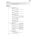
8. TEST MODE
Test Mode
A power source is put, and a playback key and a stop key are pushed after the "NO DISC" display at the same
time. (It keeps pushing it for about three seconds.)
time. (It keeps pushing it for about three seconds.)
ROM Renewal Mode
A power source is put with pushing a playback key and a halt key at the same time.
(It keeps pushing it for about three seconds.)
(It keeps pushing it for about three seconds.)
[TEST MODE]
The preparation date display of the program
10000000
∗∗∗∗∗∗∗∗
(Last updata)
Model number display
10000001 00007604
(Model number)
The version display of the program
10000002
∗∗∗∗∗∗∗∗
(Program ver.)
Reagion number display
10000003 00000008
(Region code:Binary display)
Color bar display
20000001 00000000 (FIP)
Micro-code number display
10000004
∗∗∗∗∗∗∗∗
(Microcode ver.)
The preparation date display of the servo program
10000005
∗∗∗∗∗∗∗∗
(Servo ver.)
It is returned to the test mode initial image plane.
<The "2" key of the remote controller is pushed.>
<The "1" key of the remote controller is pushed.>
Test mode initial image plane
F0000000 00000000
The "playback" key of the remote controller is pushed.
The "playback" key of the remote controller is pushed.
The "playback" key of the remote controller is pushed.
The "reactivation" key of the remote controller is pushed.
The "playback" key of the remote controller is pushed.
"Playback" key
Servo DSP Microcode version
10000006
∗∗∗∗∗∗∗∗
It is returned to the test mode initial image plane.
The "playback" key of the remote controller is pushed.
The "playback" key of the remote controller is pushed.
There is no copy guard signal.
As for the symptom when it was
dubbed in the video tape recorder?
As for the symptom when it was
dubbed in the video tape recorder?
Color bar display
20000002 00000000 (FIP)
The "playback" key of the remote controller is pushed.
AGC only
As for the symptom when it was
dubbed in the video tape recorder?
As for the symptom when it was
dubbed in the video tape recorder?
Color bar display
20000003 00000000 (FIP)
The "playback" key of the remote controller is pushed.
AGC+Color stripe1
As for the symptom when it was
dubbed in the video tape recorder?
As for the symptom when it was
dubbed in the video tape recorder?
AGC+Color stripe2
As for the symptom when it was
dubbed in the video tape recorder?
As for the symptom when it was
dubbed in the video tape recorder?
Color bar display
20000003 00000000 (FIP)
To (1)
The all FIPs burning
40000000 00000000 (OSD only)
<The "4" key of the remote controller is pushed.>
<"3" key input>
The "4" key of the remote controller is pushed.
Model name Model number
DV-750
DV-750
00007503
DV-750TK
00007503
Model name Reagion cord
DV-750
DV-750
00000004
DV-750TK
00000004
Micro-code is the thing of the process
program of the system integrated circuit.
program of the system integrated circuit.
DV-620H
DV-620S
DV-620S
14
From (1)
To (2)
LASER TEST
30000001 00000000
DYNMIC TEST
30000000 00000000
LASER TEST
30000001 00000000
STEP TEST
DD000200 00000000
"1" Key input
"1" Key input
"Open/Close" Key input
"Playback" Key input
"1" Key input
Tray opens, and laser burns.
Spin rotation, slead circumference movement
Because a tray opens, a disk is published.
Focus on
STEP TEST
DD000201 00000000
"Playback" Key input
Track on
STEP TEST
DD000202 00000000
"Playback" Key input
Focus balance adjustment (1)
STEP TEST
DD000203 00000000
"Playback" Key input
RF, Focus, Track gain adjustment
STEP TEST
DD000211 00000000
"Playback" Key input
Focus balance adjustment (2)
Control data lead
Control data lead
STEP TEST
DD000212 ********
(******* is a sector ID)
After the focus balance of layer 1,
the RF gain, the focus gain adjustment,
following playback state
the RF gain, the focus gain adjustment,
following playback state
Laser test mode
STEP TEST
30000001 00000000
"2" Key input
Step execution mode
DV-620H
DV-620S
DV-620S
15
From (2)
PLAY TEST
30000001 00000000
PLAY TEST
DD000303 ********
(SPIN)
(00000000 00000000)
"3" Key input
"Open/Close" Key input
Because a tray opens, a disk is published.
It becomes following playback state.
(******** is a sector ID.)
(******** is a sector ID.)
A test jump can be done by inputting the following key
from the remote controller.
The offset adjustment of the spindle is done automatically.
TRACK
000000** 000000++
ADJUST COMPLETE
00**00** 000000**
"Retern" key input
"Rapid return" key
"Return" key
Following playback, jump test mode
FOCUS
000000** 000000**
FOCUS
000000** 000000++
"Menu" Key input
Offset adjustment mode
1
-1
3
1
4
-102
6
102
7
-510
9
510
C
-511
M
511
2
-765
Repeat
765
5
-766
A-B
766
8
-7000
Program
7000
Before skipping.
-15000
After skipping.
15000
Next replay Layer Jump
Key
Jump
Key
Jump
Connect the L side of the voltmeter to the IC702 (pin 18) and
its H side to the IC702 (pin 17).
Adjust the output voltage to a range of -30mV to +10mV with
the cross key "
its H side to the IC702 (pin 17).
Adjust the output voltage to a range of -30mV to +10mV with
the cross key "
↑
" or "
↓
".
With the cross joint key "
←
",
→
, 5 step change
FOCUS offset adjustment mode
Connect the L side of the voltmeter to the IC702 (pin 16) and
its H side to the IC702 (pin 15).
Adjust the output voltage to a range of -30mV to +10mV with
the cross key "
its H side to the IC702 (pin 15).
Adjust the output voltage to a range of -30mV to +10mV with
the cross key "
↑
" or "
↓
".
With the cross joint key "
←
",
→
, 5 step change
TRACK offset adjustment mode
For the section of **, the adjustment results are displayed.
The indication contents mean the "focus offset adjustment value",
"track offset adjustment value" and "spindle offset adjustment value"
from the left.
Cut a power source when you finish adjustment.
Push a "Rapid return" key when it is adjusted again.
When a "return" key is pushed, it is returned in the beginning of
servo adjustment mode.
End of adjustment
After it confirms that a spindle motor stops, "RETURN"key input
The part of ++ is changed
at every key input.
at every key input.
The part of ++ is changed
at every key input.
at every key input.
[ROM RENEWAL MODE]
1. A DVD itself and a personal computer are articulated as the right figure. Software for the renewal is started more.
2. A power source is put with pushing a DVD's own playback key and a halt key at the same time. (It keeps pushing it for about three
2. A power source is put with pushing a DVD's own playback key and a halt key at the same time. (It keeps pushing it for about three
seconds.)
3. When "a lateral" is inputted in accordance with the personal computer display and data transfer indication is shown and renewal
process is started normally when an ENTER key is pushed.
4. When renewal is completed normally.
5. "STOP" key is surely pushed if renewal is completed and the display
of above NO.4 is confirmed.It is made to turn off POWER after that.
R : OK
It is displayed.
W : STR
It is displayed.
W : END
It is displayed.
Personal computer
(DOS)
DVD itself
DIGITAL It is articulated to the
OUT terminal connection child.
OUT terminal connection child.
Fixture for the ROM renewal
DV-620H
DV-620S
DV-620S
16
9.
TR
OUBLESHOO
TING
Is the fuse normal?
See FLOW CHART No.3 <The fuse blows out.>
Is normal state restored when once unplugged
power cord is plugged again after several
seconds?
Replace the fuse.
Is the AT 5V line voltage normal?
Check for leak or short-circuiting of primary
circuit component?
(Q9007, Q9010, D9016, T9001, D9013, C9021-2,
etc.)
Is the voltage of AT 12V, AT -30V and filament
voltage normal?
Check each rectifying circuit of secondary circuit.
No
Does the change from STANDBY LED indicate
turn-off?
Is the supply voltage of 5V fed to pins(15) and (16)
of IC8201?
Check the AT 5V line.
Yes
Is the supply voltage about 5V fed to pin(3) of
IC8201?
Check the IC8202.
Is there 4.0MHz oscillation at pins(1) and (2) of
IC8201?
Check the FL8201 and IC8201.
Does the "L" signal inputted at pin(14) of IC8201,
when the POWER button activated on the DVD?
Check the S8101 and POWER KEY line.
The STANDBY LED indicate it flashing after 0.5sec.
Does the remote control "L" signal inputted at
pin(4) of IC8201, when the POWER button
activated on the remote control unit?
Check the line between the remote control
receiver and the pin(4) of IC8201.
Replace IC8201.
Are the "P–CON(L)" pulse outputted from the
pin(7) of IC8201?
Replace IC8201.
Does the P–CON switch circuit is operate normally?
(Q9020-1, Q9023, Q9025-7, IC9003-4, D9030,
D9042-3, D9046)
Check each component and if poor the replace.
Is there leaking or short-circuited primary
component?
Check for short-circuiting of rectifying diode and
circuit in each rectifying circuit of secondary side.
Replace IC8201.
Are the "H" pulse inputted into the pin(9) of IC8201?
Check or replace D9035-9, D9044-5.
Yes
Yes
Yes
Yes
Yes
Yes
Yes
Yes
Yes
Yes
Yes (below, confirmed operating at LED turn-off of 0.5sec interval.)
No
No
Yes
The power cannot be turned on.(1)
No
No
No
No
No
No
No
No
No
No
No
The power cannot be turned on.(2)
FLOW CHART NO.1
FLOW CHART NO.2
FLOW CHART NO.3
The fuse blows out.
FLOW CHART NO.6
Is the supply voltage of 5V fed to pin(14) and pin
(38) of IC5001?
Check the PC 5V line.
Is the supply voltage of -19V fed to pin(27) of
IC5001?
Check the PC -19V line and Q9025.
Check R5014-5, IC5001 and their periphery.
Is there 500kHz oscillation at pin(44) of IC5001?
Check the signal lines of FIP DA, FIP CK, FIP CS
of IC5001 and IC504.
Check or replace IC5001 and IC504.
FLOW CHART NO.7
No
Is key switch contact and installation state normal?
Replace key switch.
Is the control voltage normally into the pins(95)
and (96) of IC504?
Check the power circuit, D5004 and Q9026.
Check that the fluorescent display tube is free from
damages such as crack.
Are the filament voltage applied between (1), (2)
and (31), (32) of the fluorescent display tube?
Also negative voltage applied between these pins
and GND.
Check the fluorescent display tube and its periphery?
FLOW CHART NO.4
Does the secondary side photocoupler circuit
operate normally?
Check the circuit and replace the parts.
(D9020, D9041, D9046, Q9028, etc.)
Does the primary side photocoupler circuit
operate normally?
Check the circuit and replace the parts.
(D9020, D9023, D9040, etc.)
FLOW CHART NO.5
Check for short-circuiting of rectifying diode and circuit in each rectifying circuit of secondary side.
(D9005-8, D9025, IC9001-4, Q9020-1, Q9023, Q9025-7, etc.)
Replace D9020.
No
No
No
No
No
No
No
No
When the output voltage fluctuates.
Yes
Yes
Yes
Yes
Yes
Yes
Yes
Yes
When buzz is heard from the vicinity of power circuit.
The fluorescent display tube does not light.
The key operation is disabled.
KEY-1/2
3.3V
2.5V
1.8V
0.9V
0V
KEY–2
KEY–1
OFF
S8104
STILL/PAUSE
S8103
STOP
S8105
PLAY
Display

