Sharp BD-HP21H (serv.man2) Service Manual ▷ View online
BD-HP21U/S/H/A/X/RU/SB,BD-HP50U/X
2 – 1
BDHP21U
Service Manual
CHAPTER 2.
TROUBLESHOOTING TABLE
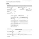
[1] MAIN
(BD-HP21/50 Series)
The main PWB circuit doesn't function when the power is turned ON.
The power does not become ON.
Is the level of pin (6) of SC9101 at Low?
The power becomes OFF.
Check the POWER pwb.
Check the
IC9001, 9002, 9003, 9004. 9005
and their peripheral circuits.
IC9001, 9002, 9003, 9004. 9005
and their peripheral circuits.
YES
NO
NO
NO
Is the fan turning on when the power
is turned ON?
is turned ON?
Check the fan, fan power and their
peripheral circuits.
peripheral circuits.
YES
YES
NO
YES
YES
FLOW CHART No.1
NO
Are AT_9V, AT_5V, SUB_PC-8V,
SUB_PC_5V supplied to SC9001?
SUB_PC_5V supplied to SC9001?
Check the power PWB.
YES
NO
Is 1.05V supplied to TL9019 and TL9016,
3.3V to TL9017, 1.8V to TL 9018 and
TL9020 respectively?
3.3V to TL9017, 1.8V to TL 9018 and
TL9020 respectively?
Check the IC9001, 9002, 9003, 9004, 9005
and their peripheral circuits.
and their peripheral circuits.
YES
NO
Is the level of pin (14) of CN5601 at High?
Check R5626 and the analog PWB.
YES
NO
Is 27MHz detected at R7326?
Check X7201 and its peripheral circuits.
YES
NO
Does pin (1) of CN7203 turn to High and
Low on start-up?
Low on start-up?
Check IC7802, IC7803, IC7804, IC7805,
IC8502, IC8505 and their peripheral
circuits.
IC8502, IC8505 and their peripheral
circuits.
Check IC7201 and its peripheral circuits.
The drive doesn't function normally.
Are 12V and 5V supplied to the drive?
Check the power PWB, BD_12V, BD_5V and their peripheral
circuits.
circuits.
NO
YES
Is the SATA cable connected CN8102 and drive certainly?
Check the connection of CN8102 and drive.
NO
YES
Pin 2, 3, 5, 6 of CN8102 occasionally turn to low.
Check the peripheral circuits of IC7201.
NO
YES
Check the drive.
FLOW CHART No.2
BD-HP21U/S/H/A/X/RU/SB,BD-HP50U/X
2 – 2
No video signal output from the main PWB.
Is video signal input into each terminal of SC5601?
1) S-VIDEO and COMPOSIT OUTPUT TERMINALS
2 pins (SUB_YOUT), 4 pins (SUB_COUT)
2) D-VIDEO TERMINAL
6 pins (MAIN_YOUT), 8 pins (MAIN_PBOUT),
10 pins (MAIN_PROUT)
1) S-VIDEO and COMPOSIT OUTPUT TERMINALS
2 pins (SUB_YOUT), 4 pins (SUB_COUT)
2) D-VIDEO TERMINAL
6 pins (MAIN_YOUT), 8 pins (MAIN_PBOUT),
10 pins (MAIN_PROUT)
NO
YES
Is video signal input into the base of transistor for each buffer?
1) S-VIDEO and COMPOSIT OUTPUT TERMINALS
Q5604, Q5605
2) D-VIDEO TERMINAL
Q5601, Q5602, Q5603
1) S-VIDEO and COMPOSIT OUTPUT TERMINALS
Q5604, Q5605
2) D-VIDEO TERMINAL
Q5601, Q5602, Q5603
Check SUB_PC_5V line.
Check SC5601.
YES
NO
Check IC7201.
FLOW CHART No.3
No audio signal output from the main PWB
Is audio signal input into terminal of each connector?
1) 2ch analog audio connection
Pins (12) (MAIN_L) and (14) (MAIN_R) of SC5601.
1) 2ch analog audio connection
Pins (12) (MAIN_L) and (14) (MAIN_R) of SC5601.
YES
NO
Is there output from DAC?
1) 2ch analog audio connection
Check pins (9) and (10) of IC5606.
1) 2ch analog audio connection
Check pins (9) and (10) of IC5606.
Check the peripheral circuits of SC5601.
Check the ANALOG pwb.
YES
NO
Is 5V supplied to pin (13) and -8V to pin (11) of IC5606
respectively?
respectively?
Check the peripheral circuits of IC5602.
NO
Replace IC5606.
YES
YES
Is any digital signal input into pins (1) - (4) of the IC5606?
Check the peripheral circuits of IC7201.
Check the line between each resistor and IC5606.
YES
NO
NO
Is any digital signal detected at each resistor of R7304 to
7315?
7315?
FLOW CHART No.4
BD-HP21U/S/H/A/X/RU/SB,BD-HP50U/X
2 – 3
No video and audio signal output from HDMI terminal.
Replace the TV set (cable) and reconfirm.
Still no video and audio output?
Still no video and audio output?
YES
NO
Is level of R4218 higher than 2V?
Is the level of pin (5) of IC4203 at least 5V?
Defective TV set or cable. Or, check the contact of soldered
connector of SC4201.
connector of SC4201.
NO
NO
Are output voltages of IC4201 as 1.0V, IC4203 as 5V,
IC4206 as 3.3V OK?
IC4206 as 3.3V OK?
Check the IC4201, IC4203 and IC4206 or peripheral circuits.
NO
YES
Is the data line functioning (Hi/Low)?
Check IC7802, IC7803, IC7804, IC7805, IC8502, IC8505 and
their peripheral circuits.
their peripheral circuits.
Replace IC7201.
Or rewrite the main software.
Or rewrite the main software.
NO
YES
FLOW CHART No.5
No audio signal output from the Optical and *Coaxial terminal.
Is there digital audio signal at R5669?
YES
NO
Check the IC7201 and their peripheral circuits.
Check the J5601 and CN5602 and the peripheral circuits.
FLOW CHART No.6
*Coaxial terminal is HP50 only.
BD-HP21U/S/H/A/X/RU/SB,BD-HP50U/X
2 – 4
[2] ANALOG
(BD-HP21 Series)
No picture appears with the component or composite signal.
Is the video signal outputted from the component or
composite terminal J2401?
composite terminal J2401?
YES
NO
* Is the component output sent to the component
terminal if selected?
terminal if selected?
Select the component output with the remote controller.
Hold down the HDMI button on the remote controller.
CP-oP: Component output
H-oP: HDMI output
Hold down the HDMI button on the remote controller.
CP-oP: Component output
H-oP: HDMI output
Mount C2301, C2306, C2313, C2317 and C2320 in place.
If no signal comes in, replace IC2301.
(When the 5V signal is fed to pins (7) and (21) of IC2301.)
If no signal comes in, replace IC2301.
(When the 5V signal is fed to pins (7) and (21) of IC2301.)
Are pins (2) (composite, S-Video terminal output mute) and
(13) (component output mute) of IC2301 at "H" level?
("H": Mute)
(13) (component output mute) of IC2301 at "H" level?
("H": Mute)
Disconnect the output coupling capacitors C2305, C2314, C2318
and C2321. If no signal comes out of the IC, replace this IC.
and C2321. If no signal comes out of the IC, replace this IC.
Check the connected cable and its connection tightness.
Check also the input of connected TV set.
Check also the input of connected TV set.
Disconnect CN2302.
Is there the signal at each terminal of SC5601?
Is there the signal at each terminal of SC5601?
Check the PMUTE1, PMUTE2
and F_MUTE lines.
and F_MUTE lines.
Check IC2301 and its
peripheral circuits.
Or replace IC2301 as required.
peripheral circuits.
Or replace IC2301 as required.
NO
YES
Is the video signal inputted to the component or composite
terminal J2401?
terminal J2401?
Check each terminal.
Check the line between IC2301 and each terminal.
NO
YES
Are there the following input signals at the CN2302 terminals?
Ԙ Component
Ԙ Component
pin (6)
MAIN_Y
pin (8)
MAIN_PB
pin (10)
MAIN_PR
ԙ Composite
pin (2)
SUB_Y
pin (4)
SUB_C
MAIN FLOW CHART No.3
NO
NO
NO
YES
YES
YES
NO
YES
Are there the following input signals at the IC2301 terminals?
Ԙ Component
Ԙ Component
pin (8)
CY_IN
pin (10)
CB_IN
pin (12)
CR_IN
ԙ Composite
pin (1)
C_IN
pin (3)
Y_IN
Are there the following output signals at the IC2301 terminals?
Ԙ Component
Ԙ Component
pin (20)
CY_OUT
pin (17)
CB_OUT
pin (15)
CR_OUT
Ԛ Composite
pin (25)
V_OUT
Check the line between CN2302 and IC2301.
NO
Check the SUB_PC_5V line.
Is the SUB_PC_5V signal fed to pins (7) and (21) of IC2301?
NO
YES
YES
FLOW CHART No.1

