Sharp XL-HP600 (serv.man3) Service Manual / Parts Guide ▷ View online
XL-HP600E
A
B
C
D
E
F
G
H
1
2
3
4
5
6
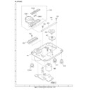
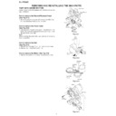
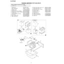
Figure 7 CD MECHANISM EXPLODED VIEW
– 7 –
701
304
701
302
301
702
303
M1
703x2
305x2
SW4
M2
308
PWB-D
306-2
306
704
307
306-1
306-3
XL-HP600E
A
B
C
D
E
F
G
H
1
2
3
4
5
6
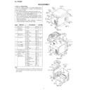
Figure 8 CD CHANGER MECHANISM EXPLODED VIEW
– 8 –
CD MECHANISM
PWB-E
102
102
101
102
101
111
136
804
106
108
805
805
805
140
804
139
80mm
119x3
MOB1
104
SWB101/102
SWB103/104
SWB103/104
,
SWB
105
105
SWB
106
106
SWB
108 SWB
108 SWB
107
MOB2
802x2
802
x2
138
110
120
103
122
107
131 124
125
129
122
131
132
108
117x2
116x2
132
137
132
803
126
133
127
115
109
114
113
129
129x3
128
130
112
130
806x3
101
118
134
135
806
121
801x4
118
121
118
121
129
129x3
128
130
112
130
129
129x3
128
130
112
130
XL-HP600E
A
B
C
D
E
F
G
H
1
2
3
4
5
6
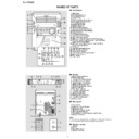
Figure 9 CABINET EXPLODED VIEW
– 9 –
,,,
,,,
yyy
yyy
,
y
,
y
,,
,,
yy
yy
FAN POSITION.
CAUTION : RING SPRING ASSY.INTO
FAN RIB
RING GAP
FAN RIB
RING GAP
MOTOR.
AFTER FULLY INSERTED THE FAN TO
CAUTION : MUST VISUAL CHECK
4.9mm
FAN MOTOR BRACKET.
FAN BLADE
MOTOR BRACKET.
GAP IS 4.9 mm BETWEEN FAN AND FAN
( FOR REFERENCE ONLY )
OK
NG
FF/REW
Clutch
FF/REW
Belt
Main
Belt
Flywheel
BELT CONNECTION
Motor
Flywheel
Silicon
Grease
Grease
Silicon
Grease
Grease
PWB-A2
PWB-A1
PWB-C
PWB-B1
FL701
PWB-B2
PWB-A4
PWB-A3
CD CHANGER
MECHANISM UNIT
A
A
B
B
201
201-1
201-6
201-7
201-9
201-20
201-21
201-2
201-11
201-10
201-13
202-1
202
204
205
206
207
202-2
201-12
201-17
203-1
203-2
203
201-18
201-16
230
208
215
201-3 201-19
201-14
210
211
216
212-1
228x8
210-1
210-2
210-3
210-4
210-5
210-6
210-7
210-8
210-2
210-3
210-4
210-5
210-6
210-7
210-8
232
221
201-4
201-5
227
229
229
217
218
212-4
606x2
611x2
602
222
212-2
212
213
226
214
201-8
225
617
610x4
616x2
614x3
601
603x2
603x2
603x2
608x3
608x2
608x2
609x2
609x2
614x14
605x2
604x3
614x3
607x9
613
612x4
613x2
607
212-3
(M971)
Note: Only the unit and consumable parts are supplied as parts supply for the Tape mechanism.
XL-HP600E
– 10 –
A
B
C
D
E
F
G
H
1
2
3
4
5
6
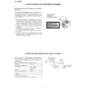
Figure 10 SPEAKER EXPLODED VIEW
903
902
902-1
902-2x2
902-3x2
902-2x2
902-3x2
903-1
903-2
901
901-1
901-2
901-4
904
901-6
901-5
905x2
906x4
SP1,2
SP3,4
901-3x4
TWEETER
SP1(L-CH)
SP2(R-CH)
WOOFER
SP3(L-CH)
SP4(R-CH)
Capacitor
2.2
µ
,100V
Capacitor
2.2
µ
,100V
TWEETER
SP1(L-CH)
SP1(L-CH)
SP2(R-CH)
WOOFER
SP3(L-CH)
SP4(R-CH)
BK
BK
RED
RED
Display

