Sharp XL-70 (serv.man6) Service Manual ▷ View online
XL-60H/70H
– 18 –
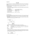
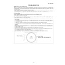
B) Cautions concerning the ASPM test mode
a) Cancel: When the "ASPM" button is pressed again during operation after it was first pressed in the test mode, the ASPM
a) Cancel: When the "ASPM" button is pressed again during operation after it was first pressed in the test mode, the ASPM
test mode is canceled (interrupted), and the initial state FM 106.50 MHz (ST) indication is restored.
(To check the data which was preset and stored until interruption, use the preset UP/DOWN button. (JOG UP/DOWN is
also available after JOG mode button operation.)
wing indication appears.
b) The ASPM test mode is started in FM stereo state (FM 106.50 MHz ST). If any button other than ASPM button is pressed
even only once after it is started, it becomes invalid, and the ASPM test mode becomes inoperable.
Invalid: The Ordinary mode is set while 4 to 30CH data remain in memory (or 1 to 30 CH MAX data remain in memory).
The "ASPM" button can be repeatedly operated until 01CH to 03CH is filled (up to 3 stations in memory).
The number of stored stations -> Channel No. -> Frequency -> FM 106.50 MHz (ST) is indicated.
(1 second) (1 second) (1 second) (Initial state)
The number of stored stations -> Channel No. -> Frequency -> FM 106.50 MHz (ST) is indicated.
(1 second) (1 second) (1 second) (Initial state)
c) Broadcast (without PI code) which is not RDS is not preset and stored in memory.
When the ASPM mode is set, the "MEMORY/SET" button cannot be operated (the test mode is canceled).
Operation is possible after ASPM test mode operation.
When the ASPM mode is set, the "MEMORY/SET" button cannot be operated (the test mode is canceled).
Operation is possible after ASPM test mode operation.
d) Scan frequency: 105.00 MHz -> 108.00 MHz
Data are stored in memory so that the PI code is not duplicated (by seeing the PI code and VSM (S meter value). When
Data are stored in memory so that the PI code is not duplicated (by seeing the PI code and VSM (S meter value). When
the PI code is duplicated, both VSM (S meter value) are compared. The greater one is stored in memory but the smaller
one is discarded.
one is discarded.
For the stations having the same PI code, only one station having the highest electric field intensity is stored, and the
memory is refilled. The channels which can be preset in the ASPM test mode are 01 to 03CH. If 3 stations are stored, 30
CH are filled.
CH are filled.
For the stations having the same electric field intensity, the former (preceding station) is stored.
e) Signal of already stored same frequency is not stored. (The previously stored data is kept.)
f) The order of preset memory is 01CH -> 02CH -> 03CH.
Up to 3 stations (1 to 3CH) can be indicated. This indication is
given only in the ASPM test mode. In other mode (not in ASPM
test mode) the number of stored stations -> END is indicated
given only in the ASPM test mode. In other mode (not in ASPM
test mode) the number of stored stations -> END is indicated
* When the "PRESET UP" button or "PRESET DOWN" button is pressed after completion, the following indication appears.
* If signal exists at 106.50 MHz, the following indication appears.
In case of memory storage with ASPM, for example, if RDS station 107.50 MHz has the PI code (the same as that of RDS
station 105.50 MHz) and VSM is greater than 105.50 MHz (PR-01), data is overwritten on 105.5 MHz which is contained in
"PR-01". (Frequency is changed to 107.50 MHz.)
If VSM is equal, previously stored 105.50 MHz remains.
station 105.50 MHz) and VSM is greater than 105.50 MHz (PR-01), data is overwritten on 105.5 MHz which is contained in
"PR-01". (Frequency is changed to 107.50 MHz.)
If VSM is equal, previously stored 105.50 MHz remains.
When RDS station is stored in the test mode, the 2-second blinking of preset No. is not performed so as to save the production
line test time. ("RDS" lighting is performed.)
line test time. ("RDS" lighting is performed.)
Note: RDS operation is performed in FM MONO state. However, in case of ASPM, ASPM scan is performed after BAND is
changed from FM MONO to FM STEREO.
Note: When the
(PLAY) button is pressed in TEST 2 mode, it is possible to check the sate of IF count. However, this
function is for designer. It is not necessary for other sections.
CH indication
(for 2 seconds)
(for 2 seconds)
Frequency indication
(for 2 seconds)
(for 2 seconds)
Time series indication of PS name indication is enabled.
(The same as in case of Ordinary)
(The same as in case of Ordinary)
NO PS
(Blinking for 5 seconds: 1 Hz)
Note: If PS is fixed after the frequency indication is
resumed, the PS name indication is restored.
FM 106.50 MHz
When the PS data is given in case of NO PS indication, the
PS name indication is restored.
PS name indication is restored.
PS name
Note: If PS is fixed after the frequency indication is
resumed, the PS name indication is restored.
NO PS
(Blinking for 5 seconds: 1 Hz)
– 19 –
XL-60H/70H
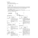
4. Electronic volume Test Mode (TEST 3)
When the test mode is set, the following indication lights for one second.
When this mode is set, BASS/TREBLE is set to 0 (0 dB) and SURROUND mode is set to off, and start-up function is set to CD
when volume is -14 dB (STEP 17). The button operations in the test mode are the same as those of ordinary operation excepting
sound volume UP/DOWN.
when volume is -14 dB (STEP 17). The button operations in the test mode are the same as those of ordinary operation excepting
sound volume UP/DOWN.
(1) The indication is the same as that of ordinary operation excepting test mode setting.
(2) The sound volume control with the sound volume UP/DOWN button is only the following 3 steps unlike the ordinary state.
(2) The sound volume control with the sound volume UP/DOWN button is only the following 3 steps unlike the ordinary state.
Volume-
∞
(STEP 0) <-> Volume-14 dB (STEP 23) <-> Volume-0 (STEP 30)
(3) BASS/TREBLE and SURROUND are switched when button operation is performed.
The current time and timer time are set in the following procedure to perform the timer playback.
1.Set the current time to 1:00, set the timer to ON time 1:02, set the function to Tape, and set volume STEP 8. One minute is counted
as one second, and the timer playback operation is performed. The fade-in (when playback is started) is executed at a rate of
one step for 0.5 sec. After completion of fade-in the fade-out is executed at a rate of one step for 0.5 sec (WAIT 1 sec inserted).
After completion of fade-out the power is turned off (after WAIT 1 sec), and the mode is changed to the standby mode.
one step for 0.5 sec. After completion of fade-in the fade-out is executed at a rate of one step for 0.5 sec (WAIT 1 sec inserted).
After completion of fade-out the power is turned off (after WAIT 1 sec), and the mode is changed to the standby mode.
The indication during operation is the same as that of ordinary timer operation.
5. Timer test Mode (TEST 4)
When the test mode is set, the following indication lights for one second.
g) When 01 to 03CH were all used, scan is aborted at the frequency at which filling occurred, and the following indication
appears.
Number of stored stations -> Indication of stored channel -> Indication of frequency -> Return to initial FM 106.50 MHz (ST)
(1 second) (1 second) (1 second)
(1 second) (1 second) (1 second)
h) If even one station could not be preset and stored in the APMS mode, "_0MEMORY" is indicated after scanning, and then
FM 106.50 MHz (ST) indication is restored. (The first digit is space.)
("_0MEMORY" is indicated in the test mode.)
i) When the "ASPM" button is pressed after three stations are stored (after full-memory of 30 stations), "ASPM" blinks for 2
seconds, and then FM 106.50 MHz (ST) indication is restored without ASPM scanning. (RDS automatic lighting)
(In case of ASPM button operation in full memory state)
j) After completion of specific operation FM 106.50 MHz (ST) indication is restored.
k) Test mode
Use of only the function button is inhibited.
Use of only the function button is inhibited.
l) The first channel to be called (when data is stored in the ASPM mode) is 01CH.
m) After start-up in the ASPM test mode the ASPM key is valid even when it is pressed many times. The test mode is kept.
If three stations are stored (1 to 3CH), full-memory state occurs.
If the ASPM button is pressed after occurrence of full-memory state, the same operation as that described in item i) is
If three stations are stored (1 to 3CH), full-memory state occurs.
If the ASPM button is pressed after occurrence of full-memory state, the same operation as that described in item i) is
performed.
In this period up to 3 stations are continuously indicated (1 to 3 CH).
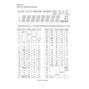
6. LCD Test Mode (TEST 5)
When the LCD test mode is set, all the LCD segments are lighted. After that the indication is changed as follows according to
the "PLAY" button input.
the "PLAY" button input.
Lighting of all segments Lighting of odd segments Lighting of even segments
XL-60H/70H
– 20 –
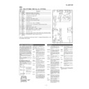
ERROR LIST
PU-IN SW detection error
CD read error
Error content ........... Disc data cannot be read properly or
even if it can be read, the disc is not a
playable one.
playable one.
Probable cause ....... The disc is loaded upside down, not CD-
DA, scratches, stains, etc.
Action ...................... Open the CD lid, then reload the disc
correctly. Remove the scratches or stains
on the disc.
on the disc.
This test mode is intended to check whether all the main unit buttons can be detected. Accordingly, in this test mode checking
as to whether the "POWER" button was pressed after all the buttons shown below were pressed is performed. If the result is
OK, OK is indicated. Even any one of keys was not pressed, an error is indicated. In case of OK termination or error termination
exit from this mode occurs when the "POWER" button is pressed next time, and the standby mode is set.
1. In case of "FUNCTION" + "RDS PTY-TP"
Since SURROUND and RDS are provided, the following 16 buttons are detected as all buttons.
PLAY, JOG MODE, BAND, BASS/TREBLE, FUNCTION, MEMORY/SET, REC PAUSE, REW, FF, STOP, CLOCK/TIMER/
SLEEP, PTY-TI, EON, APMS, DISPLAY, SURROUND
PLAY, JOG MODE, BAND, BASS/TREBLE, FUNCTION, MEMORY/SET, REC PAUSE, REW, FF, STOP, CLOCK/TIMER/
SLEEP, PTY-TI, EON, APMS, DISPLAY, SURROUND
The OK/NG indication of test result is as follows.
7. Key input diagnosis Test Mode (TEST 6)
When the test mode is set, the following indication appears.
NO DISC
Tape mechanism error 1
Tape mechanism error 2
Error content ............ The detection SW cannot detect ON
after a fixed period of time even if the
microcomputer controls the CD pickup
to return to the innermost position.
microcomputer controls the CD pickup
to return to the innermost position.
Probable cause ........ Defective or poorly connected PU-IN
SW or slide motor.
Action ....................... Solve the problem and turn on the power
again.
Error content ........... Focusing is impossible.
Probable cause ....... The disc is loaded upside down, not CD-
Probable cause ....... The disc is loaded upside down, not CD-
DA, scratches, stains, etc.
Action ...................... Open the CD lid, then reload the disc
correctly. Remove the scratches or stains
on the disc.
on the disc.
Error content ........... The detection SW "CAM-SW" cannot
detect ON (mechanism in operation) even
if the motor and solenoid are controlled
to play back, fast forward, rewind, or
record the tape.
if the motor and solenoid are controlled
to play back, fast forward, rewind, or
record the tape.
Probable cause ....... Mechanism is in operation when this
message appears: Defective or poorly
connected CAM-SW. Mechanism stops:
Defective or poorly connected motor or
solenoid.
connected CAM-SW. Mechanism stops:
Defective or poorly connected motor or
solenoid.
Action ...................... Solve the problem and turn on the power
again.
Error content ........... Initialization cannot be completed when
the microcomputer controls the motor
and solenoid to initialize the tape
mechanism (to set the mechanism to the
stop mode). The detection SW "CAM-
SW" cannot detect OFF While the
mechanism is in operation.
and solenoid to initialize the tape
mechanism (to set the mechanism to the
stop mode). The detection SW "CAM-
SW" cannot detect OFF While the
mechanism is in operation.
Probable cause ....... Mechanism is in operation when this
message appears: Defective or poorly
connected CAM-SW. Mechanism stops:
Defective or poorly connected motor or
solenoid.
connected CAM-SW. Mechanism stops:
Defective or poorly connected motor or
solenoid.
Action ...................... Solve the problem and turn on the power
again.
Display

