Sharp XL-55 (serv.man6) Service Manual ▷ View online
– 5 –
XL-55H/65H
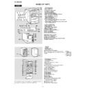
1. CD Compartment
2. CD Eject Button
3. Volume Control
4. Cassette Compartment
5. Headphone Socket
6. On/Stand-by Button
7. Function Selector Button
8. CD or Tape Stop, Tuning Down Button
9. CD Play or Pause, Tape Play,
2. CD Eject Button
3. Volume Control
4. Cassette Compartment
5. Headphone Socket
6. On/Stand-by Button
7. Function Selector Button
8. CD or Tape Stop, Tuning Down Button
9. CD Play or Pause, Tape Play,
Tuning Up Button
10. Bass/Treble Selector Button
11. Memory/Set Button
12. Tape Record Pause Button
13. CD Track Down or Fast Reverse, Tape Rewind,
11. Memory/Set Button
12. Tape Record Pause Button
13. CD Track Down or Fast Reverse, Tape Rewind,
Tuner Preset Down Button
14. CD Track Up or Fast Forward, Tape Fast Forward,
Tuner Preset Up Button
15. Timer Play Indicator
16. Tape Record Indicator
17. Sleep Indicator
18. CD Random Play Indicator
19. Memory Indicator
20. RDS Indicator
21. Traffic Programme Indicator
22. Traffic Announcement Indicator
23. FM Stereo Mode Indicator
24. FM Stereo Receiving Indicator
25. Surround Indicator
26. CD Play Indicator
27. CD Repeat Play Indicator
28. CD Digital Output Socket
29. AC Power Input Socket
30. FM 75 Ohms Aerial Socket
31. AM Loop Aerial Socket
32. Video/Auxiliary (Audio Signal) Input Sockets
33. Speaker Terminals
1
2
2
3
4
5
25
29
6
10
7
8
9
11 12
13 14
32
33
30
31
31
28
15
17 18
19
23
27
26
24
16
20 21 22
1. Tweeter
2. Woofer
3. Speaker Wire
4. Bass Reflex Duct
2. Woofer
3. Speaker Wire
4. Bass Reflex Duct
5. Remote Control Transmitter
6. Clock Button
7. On/Stand-by Button
8. CD Button
9. Tuner and Band Selector Button
6. Clock Button
7. On/Stand-by Button
8. CD Button
9. Tuner and Band Selector Button
10. Clear Button
11. Memory Button
12. CD Track Down, Tuner Preset Down Button
13. CD Fast Reverse, Tuning Down,
11. Memory Button
12. CD Track Down, Tuner Preset Down Button
13. CD Fast Reverse, Tuning Down,
Tape Rewind Button
14. CD or Tape Play Button
15. Surround Button
16. CD or Tape Stop Button
17. Volume Up and Down Buttons
18. Bass Up and Down Buttons
19. RDS Programme Type/
15. Surround Button
16. CD or Tape Stop Button
17. Volume Up and Down Buttons
18. Bass Up and Down Buttons
19. RDS Programme Type/
Traffic Information Search Button
20. Timer Button
21. Sleep Button
22. Video/Auxiliary Button
23. Tape Button
24. Repeat Button
25. Random Button
26. CD Track Up, Tuner Preset Up Button
27. CD Fast Forward, Tuning Up,
21. Sleep Button
22. Video/Auxiliary Button
23. Tape Button
24. Repeat Button
25. Random Button
26. CD Track Up, Tuner Preset Up Button
27. CD Fast Forward, Tuning Up,
Tape Fast Forward Button
28. Tape Record Pause Button
29. CD Pause Button
30. Treble Up and Down Buttons
31. RDS Display Mode Selector Button
32. RDS ASPM (Auto Station Programme Memory) Button
29. CD Pause Button
30. Treble Up and Down Buttons
31. RDS Display Mode Selector Button
32. RDS ASPM (Auto Station Programme Memory) Button
Buttons with " " mark in the illustration or highlighted in bold on
the right can be operated on the remote control only.
the right can be operated on the remote control only.
5
6
6
17
18
19
18
19
7
20
30
21
22
23
25
26
27
28
29
28
29
24
8
9
9
10
11
12
13
14
11
12
13
14
16
31
32
32
3
2
1
4
15
Speaker grilles are removable:
Make sure nothing comes into contact with the
speaker diaphragms when you remove the speak-
er grilles.
Make sure nothing comes into contact with the
speaker diaphragms when you remove the speak-
er grilles.
XL-65H
Display

