Sharp XL-55 (serv.man19) Service Manual ▷ View online
XL-55H/65H
– 44 –
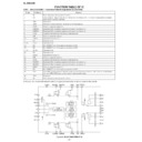
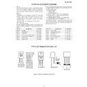
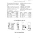
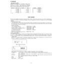
FUNCTION TABLE OF IC
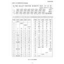
IC401 VHiLC75342M-1: Function/Volume Equaliser (LC75342M)
1
DI
Serial data and clock input pin for control.
2
CE
Chip enable pin. Data written into an internal latch in a timing of [H] -> [L]. Each analog switch is activated.
Data transfer enabled at [H] level.
Data transfer enabled at [H] level.
3
VSS
Ground pin.
4
TEST
Electronic volume control pin. To be set to the VSS potential.
5
LOUT
Volume + equalizer output pin.
6
LBASS2
Bass-band filter comprising capacitor and resistor connection pin.
7
LBASS1
Bass-band filter comprising capacitor and resistor connection pin.
8
LTRE
Capacitor connection pin comprising treble band filter.
9
LIN
Volume + equalizer input pin.
10
LSEL0
Input selector output pin.
11
L4
Input signal pin.
12-14
L3-L1
Input signal pin.
15*
NC
No CONNECT pin. To be open or connected to VSS.
16*
NC
No CONNECT pin. To be open or connected to VSS.
17-19
R1-R3
Input signal pin.
20
R4
Input signal pin.
21
RSEL0
Input selector output pin.
22
RIN
Volume + equalizer input pin.
23
RTRE
Capacitor connection pin comprising treble band filter.
24
RBASS1
Bass-band filter comprising capacitor and resistor connection pin.
25
RBASS2
Bass-band filter comprising capacitor and resistor connection pin.
26
ROUT
Volume + equalizer output pin.
27*
NC
No CONNECT pin. To be open or connected to VSS.
28
Vref
0.5 x VDD voltage generation block for analog ground. Capacitor of several 10
µ
F to be connected between
Vref and AWSS (VSS) as a counter measure against power ripple.
29
VDD
Supply pin.
30
CL
Serial data and clock input pin for control.
Pin No.
Port Name
Function
In this unit, the terminal with asterisk mark (*) is (open) terminal which is not connected to the outside.
6
7
8
9
10
11
12
13
14
15
16
17
18
19
20
21
22
23
24
25
26
5
27
28
30
29
1
2
3
4
LVref
RVref
CCB
INTERFACE
CONTROL
CIRCUIT
LOGIC
CIRCUIT
CONTROL
CIRCUIT
ROUT
RBASS1
RBASS2
RTRE
RIN RSEL0
L1
L2
L3
L4
R1
R2
R3
R4
LOUT
LBASS2 LBASS1
LTRE
LIN
LSEL0
VSS
CE
DI
CL
VDD
NC
Vref
NC
NC
TEST
Figure 44 BLOCK DIAGRAM OF IC
– 45 –
XL-55H/65H
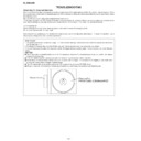
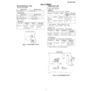
IC701 RH-iX0060SJZZ: System Control Microcomputer (IX0060SJ) (1/2)
1-4
COM3-COM0
Output
LCD common output terminal.
5-7
VLC3-VLC1
—
LCD power supply terminal.
8
VDD
—
Microcomputer power supply +5V.
9
OSC2
Output
Oscillator ground terminal for main clock. f=8MHz
10
OSC1
Input
Oscillator ground terminal for main clock. f=8MHz
11
VSS
—
Microcomputer power supply GND.
12
XI
Input
Oscillator ground terminal for sub clock. f=32.768kHz
13
XO
Output
Oscillator ground terminal for sub clock. f=32.768kHz
14
MMOD
Input
Memory mode selection terminal.
15
VREF-
—
Power supply GND for AD converter.
16
KEY0 AN0/PA0
Input
CD lid status detection input.
17
KEY1 AN0/PA1
Input
Operation button input, Max-8 buttons.
18
KEY2 AN0/PA2
Input
Operation button input, Max-8 buttons.
19
KEY3 AN0/PA3
Input
MODEL/TUNER destination input.
20*
KEY4 AN0/PA4
Input
Current detection of CD lid control motor.
Used to decide the CD lid drive error to control it.
Used to decide the CD lid drive error to control it.
21
KEY5 AN0/PA5
Input
CD servo auto adjustment mode selection input.
22
KEY6 AN0/PA6
Input
Tape mechanism operating status detection input.
Decides the F.P/CAM-SW status with A/D value.
Decides the F.P/CAM-SW status with A/D value.
23
KEY7 AN7/PA7
Input
Tuner signal meter (S meter) voltage input terminal.
24
VREF+
—
Power supply for A/D converter +5V.
25
TXD SBO0/P00
Output
Data output terminal to TUNER PLL IC.
26
RXD SBI0/P01
Input
Data input from TUNER PLL IC
27
SBT0/P02
Output
Synchronous clock output with TUNER PLL IC
28
SBO1/P03
Output
Enable output of TUNER PLL IC. "L" = OFF, "H" = ON
29
SBI1/P04
Output
Tape mechanism solenoid drive control output.
30
SBT1/P05
Output
Tape mechanism motor drive control output.
31
DK/BZER P06
Output
Recording/playback selection output of tape circuit.
"H" = Recording mode, "L" = Playback mode
"H" = Recording mode, "L" = Playback mode
32
RST/P27
Input
Reset signal input
33
RMOUT P10
Input
GVSW input.
34
P11
Input
Tape run/END detection input. Decided as tape run if pulse is input.
35
TM2IO P12
Output
Recording bias oscillation circuit control output.
"H" = Bias oscillation, "L" = oscillation stop.
"H" = Bias oscillation, "L" = oscillation stop.
36
TM3IO P13
Output
Recording bias oscillation frequency selection control output.
37
TM4IO P14
Input
Power (POWER) button input detection.
38
IRQ0 P20
Input
Switches to the HALT mode when changing to . "L" at power failure detection input.
39
SENS IRQ1/P21
Input
Remote control signal input.
40
IRQ2 P22
Input
Synchronous clock input with RDS IC.
41
IRQ3 P23
Input
Jog dial UP pulse input.
42
IRQ4 P24
Input
Jog dial DOWN pulse input.
43
P30
Output
SURROUND control output.
44
P31
Output
POWER IC STAND-BY terminal CONTROL.
45
P32
Output
Power mute output. "H" = MUTE ON, "L" = MUTE OFF
46
LED0 WE/P50
Output
CD servo power supply circuit control output. "H" = CD power ON, "L" = CD power OFF
47
LED1 RE/P51
Output
Main TRANS RELAY CONTROL. "H" = ON, "L" = OFF
48
LED2 CS/P52
Input
Data input from RDS IC.
49
LDE3/S51 A16/P53
Input
Radio stereo broadcast reception detection input. "L" = During stereo broadcast reception
50
LED4/S50 A17/P54
Input
Broadcast reception status detection input. "L" = During broadcasting signal reception
51
SEG49 P60/A0
Output
LCD backlight control signal output. "H" = Backlight ON, "L" = Backlight OFF
52*
SEG48 P61/A1
Output
Speaker relay control.
53
SEG47 P62/A2
Output
Speaker output detect.
Pin No.
Function
Terminal Name Input/Output
In this unit, the terminal with asterisk mark (*) is (open) terminal which is not connected to the outside.
XL-55H/65H
– 46 –
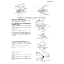
IC701 RH-iX0060SJZZ: System Control Microcomputer (IX0060SJ) (2/2)
1
2
3
4
5
6
7
8
9
2
3
4
5
6
7
8
9
10
11
12
13
14
15
16
17
18
19
20
21
22
23
24
25
11
12
13
14
15
16
17
18
19
20
21
22
23
24
25
26
27
28
29
30
31
32
33
34
35
36
37
38
39
40
41
42
43
44
45
46
47
48
49
50
75
74
73
72
71
70
69
68
67
66
65
64
63
62
61
60
59
58
57
56
55
54
53
52
51
74
73
72
71
70
69
68
67
66
65
64
63
62
61
60
59
58
57
56
55
54
53
52
51
100
99
98
97
96
95
94
93
92
91
90
89
88
87
86
85
84
83
82
81
80
79
78
77
76
O
O
O
O
O
O
O
O
I
I
O
I
I
I
I
I
I
I
I
I
I
I
I
I
I
I
I
O
I
O
O
O
O
O
I
I
I
O
O
I
I
I
I
I
I
O
O
O
O
O
O
O
I
S
S
S
S
S
S
S
S
S
S
S
S
S
S
S
S
S
O
O
O
I/O
I/O
I/O
I/O
I/O
I/O
I/O
O
O
O
I
O
O
O
O
O
O
O
O
O
O
S
S
S
S
S
S
S
S
S
S
S
S
S
S
S
S
S
S
S
S
S
S
S
S
S
COM3
COM2
COM1
COM0
COM2
COM1
COM0
VLC3
VLC2
VLC1
VLC2
VLC1
VDD
OSC2
OSC1
OSC1
VSS
XI
XO
MMOD
VREF-
CLID_SW
KEY1
KEY2
KEY2
MODEL
CLID_PRO
CD_CONF
TAPE_SW
TAPE_SW
VSM
VREF+
DI
SEG25
SEG26
SEG27
SEG28
SEG29
SEG30
SEG31
SEG32
SEG33
SEG26
SEG27
SEG28
SEG29
SEG30
SEG31
SEG32
SEG33
MCLK
MLD
MDATA
BLKCK
STAT
CD_STB
MRST
PU-IN
FAN
AMP_DEC
SP_DEC
B-LIGHT
DO
CL
CE
SOL
MOT
REC
RESET
GVSW
RUN_PLS
BIAS
B-CAN
POWER
SYS STOP
REMOCON
CLE
JOG UP
JOG DOWN
SURR
P-STB
P-MUTE
CD+B
P-CONT
DATA
STEREO
SD
SEG0
SEG1
SEG2
SEG3
SEG4
SEG5
SEG6
SEG7
SEG8
SEG9
SEG10
SEG11
SEG12
SEG13
SEG14
SEG15
SEG16
SEG17
SEG18
SEG19
SEG20
SEG21
SEG22
SEG23
SEG24
Figure 46 BLOCK DIAGRAM OF IC
Function
Terminal Name Input/Output
54*
SEG46 P63/A3
Output
Power IC amplifier detect.
55*
SEG45 P64/A4
Output
Fan control.
56*
SEG44 P65/A5
Output
57*
SEG43 P66/A6
Output
58
SEG42 P67/A7
Input
CD pickup position detection SW input. "L" = Innerst periphery
59
SEG41 P70/A8
Output
Reset signal output for MN8827482W
60
SEG40 P71/A9
Output
ON/OFF output terminal of CD servo control IC. "H" = Servo ON, "L" = Servo stand-by
61-64
SEG39 P72/A10- Input/Output
Data input/output terminal for MN8827482W control.
SEG36 P75/A13
65
SEG35 P76/A14
Output
Data synchronous clock output for MN8827482W.
66*
SEG34 P77/A15
Output
Chip enable terminal for MN8827482W. "L" = BUS terminal active
67
SEG33 P87/D7
—
LCD segment output.
68
SEG32 P86/D6
—
LCD segment output.
69-74
SEG31 P85/D5-
—
LCD segment output
SEG26 P80/D0
75-100
SEG25-SEG0
—
LCD segment output
Pin No.
In this unit, the terminal with asterisk mark (*) is (open) terminal which is not connected to the outside.
– 47 –
XL-55H/65H
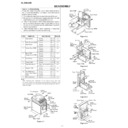
IC801 VHiMN6627482W: Servo/Signal Control (MN6627482W) (1/2)
1*
BCLK
Output
SRDATA bit clock output.
2*
LRCK
Output
L/R identification signal output.
3*
SRDATA
Output
Serial data output.
4
DVDD1
Input
Digital circuit power supply.
5
DVSS1
Input
Digital circuit GND.
6
TX
Output
Digital audio interface output signal.
7
MCLK
Input
Microcomputer command clock signal input. (Data latch at the rising edge.)
8
MDATA
Input
Microcomputer command data input.
9
MLD
Input
Microcomputer command load signal input. L: Load
10*
SENSE
Output
Sense signal output. (OFT, FESL, NACEND, NAJEND, SFG)
11*
/FLOCK
Output
Focus servo lead-in signal. (L: Lead-in)
12*
/TLOCK
Output
Tracking servo lead-in signal. (L: Lead-in)
13
BLKCK
Output
Subcode block clock signal. (fBLKCK=75 Hz)
14
SQCK, GIO0
Input
Default: external clock input for subcode Q resistor.
Command execution: general purpose I/O port.
CD-TEXT mode 2: TEXT data read clock input.
Command execution: general purpose I/O port.
CD-TEXT mode 2: TEXT data read clock input.
15*
SUBQ
Output
Subcode Q data output.
CD-TEXT mode 2: TEEXT data output.
CD-TEXT mode 2: TEEXT data output.
16
DMUTE
Input
Muting input. (Effective only at bit rate 64fs output.) H: Mute
17
STAT
Output
Status signal. (CRC, STCNT, CLVS, TTSTOP, JCLVS, SQOK, FLAG6, SENE, FLOCK,
TLOCK, revolving speed data, FCLV, SUBQ, SYFLG)
CD-TEXT mode 3: subcode Q and TEXT data output.
TLOCK, revolving speed data, FCLV, SUBQ, SYFLG)
CD-TEXT mode 3: subcode Q and TEXT data output.
18
/RST
Input
Reset input (L: Reset)
19*
SMCK
Output
MSEL=H: 8.4672 MHz clock signal output.
MSEL=L: 4.2336 MHz clock signal output.
MSEL=L: 4.2336 MHz clock signal output.
20*
PMCK, PLAY
Output
Default: 88.2 kHz clock signal output.
Command execution: Play signal output. H: play
Command execution: Play signal output. H: play
21
TRV
Output
Traverse forcing transmission output. 3-State
22
TVD
Output
Traverse drive output.
23*
PC
Output
Spindle motor ON output. L: ON (Default)
24
ECM
Output
Spindle motor drive signal. (Forcing mode output.) 3-State
25
ECS
Output
Spindle motor drive signal. (Servo error signal output.)
26
KICK
Output
Kick pulse output. 3-State
27
TRD
Output
Tracking drive output.
28
FOD
Output
Focus drive output.
29
VREF
Input
DA output section (TVD, ECS, TRD, FOD, FBAL, TBAL, TOFS) reference voltage.
30
FBAL
Output
Focus balance adjustment output.
31
TBAL
Output
Tracking balance adjustment output.
32
FE
Input
Focus error signal input. (Analog input)
33
TE
Input
Tracking error signal input. (Analog input)
34
RFENV
Input
RF envelope signal input. (Analog input)
35
VDET
Input
Oscillation detection signal input. H: Detection
36
OFT
Input
Off track signal input. H: Off track
37
TRCRS
Input
Track cross signal input. (Analog input)
38
/RFDET
Input
RF detection signal input. L: Detection
39
BDO
Input
Drop out signal input. H: Drop out
40
LDON
Output
Laser ON signal output. H: ON
41
PLLF2
Input/Output
Loop filter characteristic switch terminal for PLL.
42*
TOFS
Output
Tracking offset adjustment output. (Shared with general purpose DA output terminal.)
43*
WVEL
Output
Double-speed status signal output. H: Double-speed
44
ARF
Input
RF signal input.
45
IREF
Input
Reference current input terminal
46*
DRF
Input
DSL bias terminal.
Terminal Name
Pin No.
Input/Output
Function
In this unit, the terminal with asterisk mark (*) is (open) terminal which is not connected to the outside.
Display

