Sharp SD-EX200 (serv.man6) Service Manual ▷ View online
SD-EX200H
– 4 –
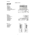
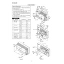
NAMES OF PARTS
SD-EX200H
Front panel
1. CD Cover
2. Remote Sensor
3. Timer Set Indicator
4. Headphone Socket
5. CD Stop Button
6. CD Play/Pause Button
7. Tuner (Band) Button
8. Auxiliary Button
9. Volume Up and Down Buttons
2. Remote Sensor
3. Timer Set Indicator
4. Headphone Socket
5. CD Stop Button
6. CD Play/Pause Button
7. Tuner (Band) Button
8. Auxiliary Button
9. Volume Up and Down Buttons
10. CD Cover Open/Close Button
11. CD Track Down or Fast Reverse/Tuning Down Button
12. CD Track Up or Fast Forward/Tuning Up Button
13. Bass/Treble Button
14. On/Stand-by Button
11. CD Track Down or Fast Reverse/Tuning Down Button
12. CD Track Up or Fast Forward/Tuning Up Button
13. Bass/Treble Button
14. On/Stand-by Button
Display
1. Surround Indicator
2. RDS Indicator
3. Radio Text Indicator
4. Traffic Announcement Indicator
5. FM Stereo Mode Indicator
6. Timer Play Indicator
7. Sleep Indicator
8. Dynamic PTY Indicator
9. Traffic Programme Indicator
2. RDS Indicator
3. Radio Text Indicator
4. Traffic Announcement Indicator
5. FM Stereo Mode Indicator
6. Timer Play Indicator
7. Sleep Indicator
8. Dynamic PTY Indicator
9. Traffic Programme Indicator
10. FM Stereo Receiving Indicator
11. CD Memory Indicator
12. Random Play Indicator
13. Function Indicators
14. CD Repeat Play Indicator
15. CD Play Indicator
16. CD Pause Indicator
11. CD Memory Indicator
12. Random Play Indicator
13. Function Indicators
14. CD Repeat Play Indicator
15. CD Play Indicator
16. CD Pause Indicator
3
4
5
4
5
2
11
12
13
5
8
9
7
10
11
13
14
12
3
1
6
7
7
8
9
9
10
4
14
15
16
15
16
1
2
Side panel
1. FM 75 Ohms Aerial Socket
2. Aerial Earth Terminal
3. AM Aerial Terminal
4. Auxiliary Input Sockets
5. Digital Output Socket
6. AC Power Lead
7. Speaker Terminals
8. Left Side Cover
9. Right Side Cover
2. Aerial Earth Terminal
3. AM Aerial Terminal
4. Auxiliary Input Sockets
5. Digital Output Socket
6. AC Power Lead
7. Speaker Terminals
8. Left Side Cover
9. Right Side Cover
1
2
3
4
5
6
2
3
4
5
6
7
Left side
Right side
8
9
6
– 5 –
SD-EX200H
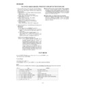
1. Tweeter
2. Speaker Grille
3. Woofer
4. Bass Reflex Duct
5. Speaker Terminals
2. Speaker Grille
3. Woofer
4. Bass Reflex Duct
5. Speaker Terminals
1
3
2
4
5
Speaker grilles are removable:
Make sure nothing comes into contact with
the speaker diaphragms when you remove
the speaker grilles.
the speaker diaphragms when you remove
the speaker grilles.
Remote control
1. Remote Control Transmitter
2. CD Play/Pause Button
3. CD Stop Button
4. Cursor/Tuner Preset Buttons
5. RDS Display Button
6. RDS Programme Type/Traffic Information Search Button
7. CD Track Down or Fast Reverse/Tuning Down Button
8. CD Memory Button
9. Programme Clear Button
2. CD Play/Pause Button
3. CD Stop Button
4. Cursor/Tuner Preset Buttons
5. RDS Display Button
6. RDS Programme Type/Traffic Information Search Button
7. CD Track Down or Fast Reverse/Tuning Down Button
8. CD Memory Button
9. Programme Clear Button
10. Surround Button
11. Timer Button
12. Enter Button
13. On/Stand-by Button
14. Auxiliary Button
15. CD Play Mode Select Button
16. Bass/Treble Button
17. Tuner (Band) Button
18. RDS ASPM (Auto Station Programme Memory) Button
19. CD Track Up or Fast Forward/Tuning Up Button
20. Volume Up and Down Buttons
21. CD/Tuner Direct Buttons
22. CD Time Display Button
23. Clock Display/Dimmer Button
2
1
3
5
4
7
6
8
10
11
12
16
17
13
14
15
18
20
21
19
9
22
23
23
Buttons with " " mark in the illustration or highlighted in bold on the list can be op-
erated on the remote control only.
erated on the remote control only.
SD-EX200H
CP-EX200H
SD-EX200H
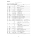
– 6 –
1
Rear Cabinet
1. Screw ...................... (A1) x7
6-1
2
Main PWB/
1. Screw ...................... (B1) x5
6-2
Tuner Unit
2. Jack Cover, Left ...... (B2) x1
3. Screw ...................... (B3) x5
4. Socket ..................... (B4) x8
5. Flat Cable ............... (B5) x1
3. Screw ...................... (B3) x5
4. Socket ..................... (B4) x8
5. Flat Cable ............... (B5) x1
3
Front Panel
1. Screw ...................... (C1) x3
6-3
2. Hook ........................ (C2) x1
3. Socket ..................... (C3) x1
3. Socket ..................... (C3) x1
4
Power PWB
1. Screw ...................... (D1) x6
6-3
2. Bracket .................... (D2) x1
5
1-Bit Amp. Unit
1. Screw ...................... (E1) x2
6-3
6
Display PWB
1. Screw ....................... (F1) x6
6-4
2. Frame Support ......... (F2) x1
3. Screw ....................... (F3) x6
3. Screw ....................... (F3) x6
7-1
4. Socket ...................... (F4) x2 6-4, 7-1
7
Headphones PWB 1. Screw ...................... (G1) x1
6-4
8
Switch PWB
1. Screw ...................... (H1) x1
7-1
9
CD Mechanism
1. Screw ....................... (J1) x6
7-1
10
Protect Circuit
1. Screw ...................... (K1) x4
7-2
PWB/1-Bit Amp.
2. Bracket .................... (K2) x2
Shield Case
3. Screw ...................... (K3) x3
11
1-Bit Amp. PWB
1. Screw ....................... (L1) x3
7-3
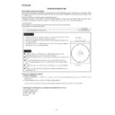
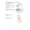
DISASSEMBLY
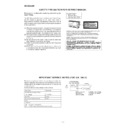
Caution on Disassembly
Follow the below-mentioned notes when disassembling
the unit and reassembling it, to keep it safe and ensure
excellent performance:
1. Take compact disc out of the unit.
2. Be sure to remove the power supply plug from the wall
Follow the below-mentioned notes when disassembling
the unit and reassembling it, to keep it safe and ensure
excellent performance:
1. Take compact disc out of the unit.
2. Be sure to remove the power supply plug from the wall
outlet before starting to disassemble the unit.
3. Take off nylon bands or wire holders where they need to
be removed when disassembling the unit. After servicing
the unit, be sure to rearrange the leads where they were
before disassembling.
the unit, be sure to rearrange the leads where they were
before disassembling.
4. Take sufficient care on static electricity of integrated
circuits and other circuits when servicing.
Figure 6-2
STEP
REMOVAL
PROCEDURE
FIGURE
Figure 6-1
Figure 6-3
SD-EX200H
(A1)x4
ø3x10mm
ø3x10mm
(A1)x3
ø3x12mm
ø3x12mm
Rear
Cabinet
Cabinet
Front
Panel
(F4)x1
(F2)x1
(F1)x6
ø3x10mm
ø3x10mm
(G1)x1
ø3x10mm
ø3x10mm
Headphones
PWB
PWB
Front Panel
Figure 6-4
(B3)x1
ø3x8mm
ø3x8mm
Main PWB
Tuner Unit
Front Panel
(B4)x4
(B4)x3
(B5)x1
(B4)x1
(B2)x1
(B1)x4
ø3x10mm
ø3x10mm
(B3)x4
ø3x10mm
ø3x10mm
(B1)x1
ø3x8mm
ø3x8mm
1-Bit Amp.
Unit
Unit
(D2)x1
(C3)x1
(C1)x3
ø3x8mm
ø3x8mm
(E1)x2
ø3x10mm
ø3x10mm
(D1)x6
ø3x10mm
ø3x10mm
Power PWB
1-Bit Amp. Unit
(C2)x1
Front
Panel
Panel
Display

