Sharp SD-EX100H (serv.man8) Service Manual ▷ View online
SD-EX100H
– 16 –
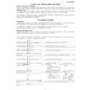
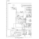
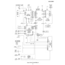
DESCRIPTION OF CIRCUIT FOR 1-BIT UNIT
(SEE THE WIRING DIAGRAMS ON PAGES 42 AND 43.)
Input
Signals over certain level input from BIA106 are sliced into
waveforms by RA173 (RA174), DA126, and DA127 (DA128,
DA129).
The slice levels depend on the output of the unit.
In case of 25 W output setting, the level is set to gain distortion
of approx. 10 % during output.
The level on the positive side is determined by RA175, RA177
and RA179 and that on the negative side by RA176, RA178,
and RA180, respectively.
After DC cut by CA109, the signals are input to AD conversion
IC.
modulation 1-bit conversion
The signals input to the AD conversion IC are converted into
1-bit signals for differential output.
For detailed technical description of 1-bit signal conversion,
refer the technical manual for SM-SX100 already published.
The signals input to the AD conversion IC are converted into
1-bit signals for differential output.
For detailed technical description of 1-bit signal conversion,
refer the technical manual for SM-SX100 already published.
Dead time and level shift
When the 1-bit signals are output from the AD conversion IC,
the leading edge of the waveform is delayed for 20 to 25 nsec
by DA103 (DA102, DA101, and DA100), RA115 (RA114,
RA113, and RA112), and CA155 (CA154, CA153, and CA152),
compared with the trailing edge.
As mentioned below, this operation is for reducing switching
circuit loss in the final stage.
The signals are input to the buffer IC (AND gate IC) for the
waveform format and are output.
Low-pass filter circuit
The 1-bit signal switched by output IC converts to analog by
going through a low pass filter comprised of LA100 (LA102,
LA104, LA106) and CA142 (CA143, CA150, CA151).
The characteristic of the low pass filter does not fluctuate up
to 20 kHz and approx. 3 dB attenuates at around 40 kHz.
The 1-bit signal switched by output IC converts to analog by
going through a low pass filter comprised of LA100 (LA102,
LA104, LA106) and CA142 (CA143, CA150, CA151).
The characteristic of the low pass filter does not fluctuate up
to 20 kHz and approx. 3 dB attenuates at around 40 kHz.
Dynamic feedback circuit
The 1-bit signal switched by output IC oscillates between +
and – power sources.
The resistance is divided to feed back the signal through NF
resistance 75 k
The 1-bit signal switched by output IC oscillates between +
and – power sources.
The resistance is divided to feed back the signal through NF
resistance 75 k
Ω
to AD conversion IC. The P-P voltage
measures approx. 5 V at this time.
Display

