Sharp SD-EX100H (serv.man6) Service Manual ▷ View online
SD-EX100H
– 8 –
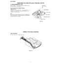
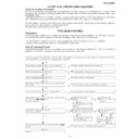
REMOVING AND REINSTALLING THE MAIN PARTS
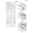
How to remove the Optical Pickup
(See Fig. 8-1)
(See Fig. 8-1)
1. Remove the stop washer (A1) x 1 pc and gear (A2) x 1 pc.
2. Remove the screws (A3) x 2 pcs and shaft (A4) x 1 pc.
3. Remove the optical pickup.
2. Remove the screws (A3) x 2 pcs and shaft (A4) x 1 pc.
3. Remove the optical pickup.
Note:
After pulling out the optical pickup connector, wrap the tip of
it with conductive aluminium foil or the like to protect the optical
pickup from the static electricity.
After pulling out the optical pickup connector, wrap the tip of
it with conductive aluminium foil or the like to protect the optical
pickup from the static electricity.
Figure 8-1
Optical Pickup
(A3)x2
ø2.6x6mm
ø2.6x6mm
CD Mechanism
Shaft (A4)x1
Gear (A2)x1
Stop Washer (A1)x1
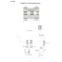
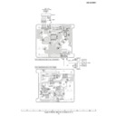
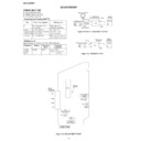
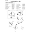
WIRING PROCESS DIAGRAM
1-BIT SECTION
Figure 8-2
CD MECHANISM SECTION
Perform steps 1 to 15 of the disassembly method to remove
the CD mechanism. (See page 5.)
the CD mechanism. (See page 5.)
Tie nylon straps around cords as illustrated.
– 9 –
SD-EX100H
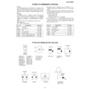
EXPLANATION OF CD MECHANISM
Description of CD Mechanism
This is a vertical loading mechanism, which carries a CD to the playback point. Direct and reverse motors, equipped with the end
detection switches, control the CDs’ movement.
detection switches, control the CDs’ movement.
Opening/closing the tray: CD up/down mechanism
The mechanism carries a CD loaded in the tray to the playback point.
Since the center position differs between 8-cm and 12-cm discs, the tray is positioned by the photo sensor.
The sensor on the right of the slot detects the 12-cm disc.
The mechanism carries a CD loaded in the tray to the playback point.
Since the center position differs between 8-cm and 12-cm discs, the tray is positioned by the photo sensor.
The sensor on the right of the slot detects the 12-cm disc.
Moving up/down the CD mechanism unit: back and forth mechanism
The mechanism moves the unit back and forth to load the medium on or unload the medium from the turntable.
When the mechanism is moved toward the front of the unit, the medium is loaded on the mechanism.
The mechanism moves the unit back and forth to load the medium on or unload the medium from the turntable.
When the mechanism is moved toward the front of the unit, the medium is loaded on the mechanism.
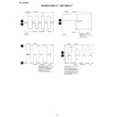
Tray position and waveform
The both end switches and the photo sensor are used for detecting the tray position.
The plate with slits for position detection passes between photo interrupters located on the reverse side of the tray.
The plate with slits for position detection passes between photo interrupters located on the reverse side of the tray.
Open END SW
Open END SW
Close END SW
Close END SW
Light receiving element
Light emitting element
Light receiving element
Light emitting element
Open END SW
Eject END
Close END SW
Position sensor
< Open >
< Close >
12cm Disc Sensor
8cm
Loading position
Loading position
12cm
Loading position
Load END
Tray opened
Photo interrupter
Tray closed
Output waveform when the tray travels
Detecting a 12-cm disc
A CD on the tray passes between the photo interrupters. The signal is not detected when no CDs or an 8-cm CD is loaded.
SD-EX100H
– 10 –
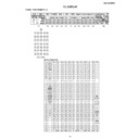
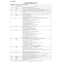
Control Input/Output
The following terminals are used for control.
Microcomputer input terminal
Microcomputer output terminal
Name
Type
Descriptions
SW_Tray Eject
H/L
Switch input for tray eject completion detection
L: Position "Ejected"
H: other positions
H: other positions
SW_Tray Load
H/L
Switch input for tray loading completion detection
L: Position "Loaded"
H: other positions
H: other positions
SW_Mecha Up
H/L
Switch input for mechanism up completion detection
L: "UpEnd" position
H: other positions
H: other positions
SW_Mecha Down
H/L
Switch input for mechanism down completion detection
L: "DownEnd" position
H: other positions
H: other positions
PH_12cm Disc
H/L
Input of the photo sensor for detecting a 12-cm disc. The sensor detects the disc directly.
At the detection position, L : 12-cm disc
At the detection position, L : 12-cm disc
H : Others (interpreted as 8-cm disc)
PH_Tray
H/L
Input of the photo sensor for detecting the tray position. The tray is covered with a piece of tape.
L: a covered tray
H: a non-covered tape. Parts not covered, or a slit.
H: a non-covered tape. Parts not covered, or a slit.
Sens_Jaming
A/Din
Port for overcurrent detection of the mechanism up/down motor
Port voltage > 1.65 V: abnormal. Considered as jamming.
Port voltage < 1.65 V: normal.
Port voltage < 1.65 V: normal.
Name
Type
Initial value
Descriptions
TRY_M+
D Aout
0V
Control output for tray control motor CW (EJECT direction)
TRY_M–
D Aout
0V
Control output for tray control motor CCW (LOADING direction)
MECHA_M+
H/L
L
Control output for mechanism up/down control motor CW (upward,
media loaded)
media loaded)
MECHA_M+
H/L
L
Control output for mechanism up/down control motor CCW
(downward, media removed)
(downward, media removed)
=
– 11 –
SD-EX100H
Initializing the mechanism
The mechanism is initialized and checked in the following cases.
1. The power is turned on for the first time after resetting the microcomputer.
2. The mechanism is not in the loading or ejecting completed state when the power is turned on.
1. The power is turned on for the first time after resetting the microcomputer.
2. The mechanism is not in the loading or ejecting completed state when the power is turned on.
Initializing the mechanism
Start
End
Mechanism up
switch
OK?
Close
Open
The tray moves downward until
the close switch is turned on.
the close switch is turned on.
The CD mechanism moves
downward until the switch is
turned on.
downward until the switch is
turned on.
The CD mechanism moves
downward until the switch is
turned on.
downward until the switch is
turned on.
The tray moves upward until
the open switch is turned on.
the open switch is turned on.
The tray moves downward until
the close switch is turned on.
the close switch is turned on.
OK
OK?
OK?
OK
OK
OK?
OK
OK?
OK
NG
Er-CD TA?O0
NG
Er-CD TA?D0
NG
Er-CD TA?C0
The open switch
is checked.
is checked.
The up/down
motor and the
down switch are
checked.
motor and the
down switch are
checked.
NG
Er-CD TA?D0
The up/down
motor and the
down switch are
checked.
motor and the
down switch are
checked.
The tray motor
and the close
switch are
checked.
and the close
switch are
checked.
NG
Er-CD TA?C0
The tray motor
and the close
switch are
checked.
and the close
switch are
checked.
Display

