Sharp QT-CD110H (serv.man3) Service Manual ▷ View online
QT-CD111H/110H
– 9 –
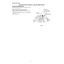
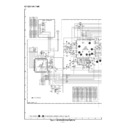
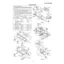
NOTES ON SCHEMATIC DIAGRAM
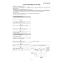
1. Tuner
( ): AM mode
Marking except for ( ): FM mode
Marking except for ( ): FM mode
2. CD
( ): Play mode
Marking except for ( ): Stop state
Marking except for ( ): Stop state
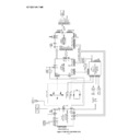
3. Deck section
( ): Record mode
Marking except for ( ): Playback mode
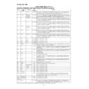
Display / Control section:
( ): Active state
Marking except for ( ): CD Function mode at stop state
Marking except for ( ): Playback mode
Display / Control section:
( ): Active state
Marking except for ( ): CD Function mode at stop state
• Schematic diagram and Wiring Side of P.W.Board for this
• Parts marked with “ ” (
) are important for
maintaining the safety of the set. Be sure to replace these
parts with specified ones for maintaining the safety and
performance of the set.
parts with specified ones for maintaining the safety and
performance of the set.
• Resistor:
• Capacitor:
• The indicated voltage in each section is the one measured by
Digital Multimeter between such a section and the chassis
with no signal given.
with no signal given.
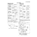
SW102
RECODE/PLAYBACK
OFF—ON
SW201
FUNCTION/POWER
TAPE—AM—
FM AUTO—CD/
OFF—ON
FM AUTO—CD/
OFF—ON
SW203
X-BASS
OFF—ON
SW601
TAPE MAIN
OFF—ON
SW702
PICKUP IN
OFF—ON
REF. NO
DESCRIPTION
POSITION
SW761
CD LID OPEN/CLOSE
OFF—ON
SW771
PLAY/REPEAT
OFF—ON
SW772
STOP
OFF—ON
SW773
TRACK UP/CUE
OFF—ON
SW774
TRACK DOWN/REVIEW
OFF—ON
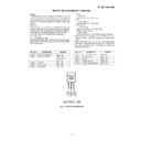
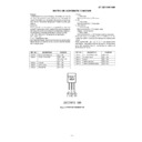
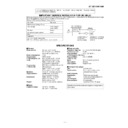
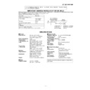
Figure 9 TYPES OF TRANSISTOR
REF. NO
DESCRIPTION
POSITION
E C B
(S) (G) (D)
(1) (2) (3)
FRONT
VIEW
2SC1815 GR
Display

