Sharp HT-CN300H (serv.man11) Service Manual ▷ View online
HT-CN300H
– 38 –
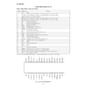
FUNCTION TABLE OF IC
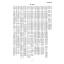
IC401 VHiLC74763/-1: OSD. (LC74763)
1
VSS
GND.
2*
XTAL IN 1
Crystal and capacitor connection in the crystal oscillator for an internal sync signal.
3*
XTAL OUT 1
Crystal and capacitor connection in the crystal oscillator for an internal sync signal.
4*
HSYNC OUT Horizontal sync signal output (AFC).
5
XTAL IN 2
Crystal and capacitor connection in the crystal oscillator for an internal sync signal.
6
XTAL OUT 2
Crystal and capacitor connection in the crystal oscillator for an internal sync signal
7*
VSYNC OUT Vertical sync signal output.
8
CS
Vertical sync signal output.
9
SIN
Serial data input (hysteresis input).
10
SCLK
Serial data input clock.
11
SECMA
SECAM mode switching at input.
12
526/625
Scan line switching (525/625) at input.
13
NTSC/PAL
Color NTSC/PAL switching.
14
3.58/4.43
3.58/4.43 MHz FSC switching.
15
RET
System reset input (active=“L”) (hysteresis input).
16
CV OUT
Composite video signal output.
17
VDD 2
Power supply for creating composite video signal levels.
18
CV IN
Composite video signal input.
19*
CV CR
SECAM chrominance signal input.
20
SYNC IN
Video signal input in the built-in sync separation circuit.
21*
SEPC
Bias input in the built-in sync separation circuit.
22
VSS
GND.
23
PD OUT
AFC control voltage output.
24
AMP IN
Filter.
25
AMP OUT
Filter.
26
FC
AFC control voltage input.
27
VCON IN
Coil and capacitor connection in the LC oscillator for VCO.
28
VCO OUT
Coil and capacitor connection in the LC oscillator for VCO.
29*
SYNC DET
EX-NOR output by horizontal sync signals (AFC) and CSYNC (sync separation).
30
VDD 1
Power supply (+5V: digital)
Port Name
Pin No.
Function
In this unit, the terminal with asterisk mark (*) is (open) terminal which is not connected to the outside.
30
VDD1
1
VSS
29
SYNCDET
2
XTALIN1
28
VCOOUT
3
XTALOUT1
27
VCOIN
4
HSYNCOUT
26
FC
5
XTALIN2
25
AMPOUT
6
XTALOUT2
24
AMPIN
7
VSYNCOUT
23
PDOUT
8
CS
22
VSS
9
SIN
21
SEPC
10
SCLK
20
SYNCIN
11
SECAM
19
CVCR
12
525/625
18
CVIN
13
NTSC/PAL
17
VDD2
14
3.58/4.43
16
CVOUT
15
RST
Figure 38 BLOCK DIAGRAM OF IC
– 39 –
HT-CN300H
IC601 RH-iX0014BGZZ: System Microcomputer (IX0014BG) (1/2)
1
VDD
VDD
Input
(+) Power supply.
2
P37
RDS READY
Input
RDS IC Ready.
3
P36
RDS RDCL/KARA LAC
Output
RDS IC Clock or karaoke latch.
4
P35
RDS RDDA/MIC IN
Input
RDS IC Data or mic in.
5
P34
RDS RESET
Output
RDS Reset.
6
P33
-20dBATT
Output
-20dB Attenuator.
7
P32
FAN CONT
Output
Fan control.
8
P31
CCB CE0
Output
CCB CE0.
9
P30
CCB CE1
Output
CCB CE1.
10
RESET
RESET
Input
Microcomputer reset.
11
X2
X2
Output
Main clock.
12
X1
X1
Input
Main clock.
13
VPP/IC
VPP/IC
—
GND.
14*
XT2
XT2
—
Open.
15
P04
SPN
Input
Tuner span select.
16
VDD
VDD
Input
(+) Power supply.
17
P27
CLK
Output
CCB/OSD/Karaoke clock.
18
P26
DATA
Output
CCB/OSD/Karaoke data.
19
P25
CCB DO INPUT
Input
CCB DO input.
20
P24
CCB CE2
Output
CCB CE2.
21
P23
FLD CS
Input
DSP Micom FL CONT CS.
22
P22
FLD SCK
Input
DSP Micom FL SCK.
23*
P21
OPEN
Output
Open.
24
P20
FLD SDATA
Input
DSP Micom FL CONT Stand.
25
AVSS
AVSS
—
Analog ground.
26
ANI7
POWER
Input
Power output level input
27
ANI6
PROTECT
Input
Protect input.
28
ANI5
THERMO
Input
Thermo level input.
29
ANI4
TUN SM
Input
Tuner signal meter.
30
ANI3
DIST 1
Input
Distination 1.
31
ANI2
DIST 0
Input
Distination 0.
32-33
ANI1-ANI0
KEY 1-KEY 0
Input
Key input.
34
AVDD
AVDD
Input
Analog VDD.
35
AVREF
AVREF
—
Analog ref voltage.
36
INTP3
SYS_STOP
Input
Power failure control.
37
INPT2
DSP RX-IN OUT
Output
Output to DSP microcomputer remcon input.
38
INTP1
DSP SYSTEM STOP
Output
DSP system stop output.
39
INTP0
REMOCON
Input
Remocon input.
40
VSS
VSS
—
Ground voltage.
41
P74
REM ACK LED
Output
Remocon acknolage LED.
42
P73
SMUTE
Output
System mute control.
43
P72
POWER ON LED
Output
Power on LED control.
44
P71
STAND BY LED
Output
Stand by LED control.
45
P70
DSP RESET
Output
DSP Microcomputer reset.
46
VDD
VDD
Input
(+) Power supply.
47
P127
DSP SMUTE IN
Input
DSP S-mute Signal input .
48
P126
DSP POWER IN
Input
DSP power on signal input.
49
P125
DD LED
Input
DSP D.D LED input.
50
P124
STD LED
Input
DSP STD LED input.
51
P123
DTS LED
Input
DSP DTS LED input.
52
P122
VIR LED
Input
DSP VIR LED input..
Port Name
Terminal Name
Pin No.
Input/Output
Function
In this unit, the terminal with asterisk mark (*) is (open) terminal which is not connected to the outside.
HT-CN300H
– 40 –
53
P121
DPL LED.
Input
DSP DPL LED input.
54*
P120
DVD DIG 2
Output
DVD DIG 2 : H.
55
P117
VIDEO OUT MUTE
Output
Video out mute : H.
56
P116
OSD CS 1
Output
ODS 1 IC chip select.
57
P115
OSD CS 2
Output
ODS 2 IC chip select. (H only)
58
P114
NTSC/PAL
Input
NTSC/PAL sw input.
59
P113
V SW 2
Output
Video select sw 2.
60
P112
V SW 1
Output
Video select sw 1.
61
P111
V REC MUTE
Output
Video REC mute.
62
P110
FUNC_DVD
Output
Function DVD : H, other :L.
63*
P107
FUNC_TUNER
Output
Function tuner : H, other : L.
64
P106
NO USE
Output
GND.
65
P105
LMUTE
Output
Line out mute control.
66
P104
AC RLY
Output
AC RLY control.
67
P103
W SP RLY
Output
Subwoofer rely control.
68
P102
S SP RLY
Output
Surround speaker rely control.
69
P101
C/W SP RLY
Output
Center speaker rely control.
70
P100
F SP RLY
Output
Front speaker rely control.
71-78
FIP28-FIP21
P20-P13
Output
FL Display segment driver.
79
VLOAD
VLOAD
Output
FL driver (-) power supply. -30 V
80-91
FIP20-FIP9
P12-P1
Output
FL Display segment driver.
92-100
FIP8-FIP0
G9-G1
Output
FL Display segment driver.
IC601 RH-iX0014BGZZ: System Microcomputer (IX0014BG) (2/2)
In this unit, the terminal with asterisk mark (*) is (open) terminal which is not connected to the outside.
Port Name
Terminal Name
Pin No.
Input/Output
Function
– 41 –
HT-CN300H
IC710 RH-iX0489AWZZ: System Microcomputer (IX0489AW) (1/2)
1
P96/ANEX1/SOUT4
FLD_SDAT
Output
Display data output to M66005FP-FL driver.
2
P95/ANEX0/CLK4
FLD_SCK
Output
Serial clock output to M66005FP-FL driver.
3
P94/DA1/TB4IN
FLD_CS
Output
CS control output to M66005FP-FL driver.
4
P93/DA0/TB3IN
FLD_RESET
Output
Reset output to M66005FP-FL driver.
5*
P92/TB2IN/SOUT3
DVD_KDATA
Output
Control data output to the DVD unit.
6
P91/TB1IN/SIN3
DVD_DATA
Input
DVD/CD/VCD data input from the DVD unit.
7*
P90/TB0IN/CLK
DVD_CLK
Output
Serial clock output to the DVD unit.
8
BYTE
BYTE
Input
Connected to VSS due to unused external bus.
9
CNVSS
FLASH_VCC
Input
Used in the single chip mode. Connected to VSS via pull-down resistance.
10
P87/XCIN
DVD_STB
Input
Strobe input from the DVD unit.
11*
P86/XCOUT
DVD_ERITE
Output
“L” - DVD microcomputer ROM write mode.
12
RESET
RESET
Input
Microcomputer reset input. Active “L”.
13
XOUT
X_OUT
Output
Microcomputer reference oscillation output.
14
VSS
GND
—
Connected to GND (VSS).
15
XIN
X_IN
Input
Microcomputer reference oscillation input
16
VCC
VCC
Input
Microcomputer power supply (3.3 V)
17
P85/MNI
FLASH_"H"
Input
Connected to VCC via pull-up resistance.
18
P84/INT2
SYS_STOP
Input
Power failure detection input. Microcomputer enters the backup mode.
19
P83/INT1
GND
—
Port processing. “L” fixed.
20
P82/INT0
RX_IN
Input
Sharp method, remote control input..
21*
P81/TA4IN/U
TIMER_LED
Output
Timer stand-by LED control.
22
P80/TA40UT/U
DD_LED
Output
Dolby digital IND.
23
P77/AT3IN
STD_LED
Output
Surround mode stanrd IND.
24
P76/TA3OUT
DTS_LED
Output
DTS IND.
25
P75/TA2IN/W
VIR_LED
Output
Surround mode virtual IND.
26
P74/TA2OUT/W
AAC_LED
Output
AAC IND.
27
P73/CTS2/RT2S/TA1IN/V
DPL_LED
Output
Dolby pro logic IND.
28
P72/CLK2/TA1OUT/V
F-CONT2
Input
Switches power supply frequency and changes oscillation frequency.
29
P71/RXD2/SCL/TA0IN/TB5IN SCL
Output
AK4586/CXA2125Q. 12C BUS clock output.
30
P70/TXD2/SDA/TA0OUT SDA
Input/Output
AK4586/CXA2125Q. 12C BUS data input/output.
31
P67/TXD1
FLASH_TXD
Output
Functionally not used. Normally, output “L” fixed.
32
P66/RXD1
FLASH_RXD
Output
Functionally not used. Normally, output “L” fixed.
33
P65/CLK1
FLASH_SLOCK
Output
Functionally not used. Normally, output “L” fixed.
34
P64/CTS1/RTS1/CTS0/CLKS1
FLASH_BUSY
Output
Functionally not used. Normally, output “L” fixed.
35
P63/TXD0
DSP_SCDIN
Output
DSP IC serial data output.
36
P62/RXD0
DSP_SCDOUT
Input
DSP IC serial data output.
37
P61/CLK0
DSP_SCCLK
Output
Sends DSP IC serial send/receive sync clock.
38
P60/CTS0/RTS0
DSP_CS
Input
Sends DSP IC serial send/receive strobe.
39
P57/RDY/CLKOUT
DSP_RESET
Output
DSP IC RESET output.
40*
P56/ALE
L-MUTE
Output
VCR OUT audio mute output.
41
P55/HOLD
FLASH_EPM
Input
Connected to VSS via pull-down resistance.
42
P54/HLDA
AUDITION
Input
Audition model select input.
43*
P53/BCLK
F_CONT
Output
Switches power supply frequency and changes oscillation frequency.
44*
P52/RD
FM_STB
Output
When function is set to “FM Stereo” or “FM MONO”: “L”. Otherwise: “H”.
45
P51/WRH/BHE
DSP_UC15
Output
External ROM for DSP download program.
46
P50/WRL/WR
FLASH_CE
Input
Connected to VCC via pull-up resistance.
47
P47/CS3
DSP_UC16
Output
External ROM for DSP download program.
48
P46/CS2
DSP_UC17
Output
External ROM for DSP download program.
49
P45/CS1
ASPECT
Input
DVD unit aspect ratio data input.
50
P44/CS0
V-MODE
Input
Video mode select SW input terminal.
51*
P43/A19
V_SEL1
Output
Connected to video output selector, SW1.
Port Name
Terminal Name
Pin No.
Input/Output
Function
In this unit, the terminal with asterisk mark (*) is (open) terminal which is not connected to the outside.
Display

