Sharp CD-MPS660H (serv.man3) User Manual / Operation Manual ▷ View online
03/12/19
CD-MPS660H(H)E1.fm
E-7
ENGLISH
CD-MPS660H
TINSZA035AWZZ
Prepar
ation for
Use
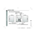
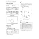
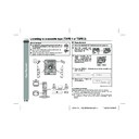
System connections
Left speaker
Right speaker
Speaker connection (see page 8)
Aerial connection (see page 8)
AC power connection (see page 9)
Wall socket
(AC 230 V, 50 Hz)
(AC 230 V, 50 Hz)
Make sure to unplug the AC power lead before any connections.
FM aerial
AM loop aerial
20
SHARP
T
INSZA0
3
5
A
W
Z
Z
Z
(H
)
)
03/12/19
CD-MPS660H(H)E1.fm
E-8
ENGLISH
8
CD-MPS660H
TINSZA035AWZZ
Prepar
ation for
Use
!
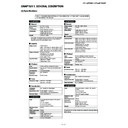
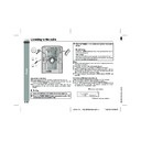
Aerial connection
Supplied FM aerial:
Connect the FM aerial wire to the FM 75 OHMS socket and position
the FM aerial wire in the direction where the strongest signal can be
received.
Connect the FM aerial wire to the FM 75 OHMS socket and position
the FM aerial wire in the direction where the strongest signal can be
received.
Supplied AM loop aerial:
Connect the AM loop aerial to the AM LOOP socket. Position the
AM loop aerial for optimum reception. Place the AM loop aerial on a
shelf, etc., or attach it to a stand or a wall with screws (not supplied).
Connect the AM loop aerial to the AM LOOP socket. Position the
AM loop aerial for optimum reception. Place the AM loop aerial on a
shelf, etc., or attach it to a stand or a wall with screws (not supplied).
Note:
Placing the aerial on the unit or near the AC power lead may cause
noise pickup. Place the aerial away from the unit for better recep-
tion.
Placing the aerial on the unit or near the AC power lead may cause
noise pickup. Place the aerial away from the unit for better recep-
tion.
Installing the AM loop aerial:
!
Speaker connection
Connect the black wire to the minus (-) terminal, and the red wire to
the plus (+) terminal.
the plus (+) terminal.
Caution:
!
Placing the speaker system
The left and right speakers have individual shapes. For best perfor-
mance, place the speakers according to the diagram below.
mance, place the speakers according to the diagram below.
Note:
The speaker grilles are not removable.
The speaker grilles are not removable.
< Assembling >
< Attaching to the wall >
Wall Screws (not supplied)
"
Use speakers with an impedance of 6 ohms or more, as lower im-
pedance speakers can damage the unit.
pedance speakers can damage the unit.
"
Do not mistake the right and the left chan-
nels. The right speaker is the one on the right
side when you face the unit.
nels. The right speaker is the one on the right
side when you face the unit.
"
Do not let the bare speaker wires touch
each other.
each other.
"
Do not stand or sit on the speakers. You may
be injured.
be injured.
Incorrect
Left speaker
Right speaker
Black
Red
21
SHARP
T
INSZA0
3
5
A
W
Z
Z
Z
(H
)
)
03/12/19
CD-MPS660H(H)E1.fm
E-9
ENGLISH
CD-MPS660H
TINSZA035AWZZ
Prepar
ation for
Use
System connections (continued)
!
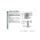
AC power connection
After checking all the connections have been made correctly, plug
the AC power lead of this unit into the wall socket. If you plug in the
unit first, the unit will enter the demonstration mode.
the AC power lead of this unit into the wall socket. If you plug in the
unit first, the unit will enter the demonstration mode.
Notes:
"
The unit will start the tape initialisation when plugged in to the AC
socket. During this process, initialising sound will be heard and
the unit cannot be turned on. Wait until the process is finished.
socket. During this process, initialising sound will be heard and
the unit cannot be turned on. Wait until the process is finished.
"
Unplug the AC power lead from the wall socket if the unit will not
be in use for a prolonged period of time.
be in use for a prolonged period of time.
!
Demonstration mode
!
External FM aerial
Use an external FM aerial if you require better reception.
Consult your dealer.
Consult your dealer.
Cooling fan:
This product is equipped with a cooling fan inside, which begins to
run at a specified volume level for better heat radiation.
run at a specified volume level for better heat radiation.
Wall socket
(AC 230 V, 50 Hz)
(AC 230 V, 50 Hz)
The first time the unit is plugged in, the
unit will enter the demonstration mode.
You will see words scroll.
unit will enter the demonstration mode.
You will see words scroll.
To cancel the demonstration
mode:
When the unit is in the power stand-
by mode (demonstration mode),
press the X-BASS/DEMO button.
The unit will enter the low power
consumption mode.
To return to the demonstration mode:
When the unit is in the power stand-by mode, press the X-BASS/
DEMO button again.
Note:
When the power is on, the X-BASS/DEMO button can be used to se-
lect the extra bass mode.
External FM aerial
03/12/19
CD-MPS660H(H)E1.fm
E-10
ENGLISH
8
CD-MPS660H
TINSZA035AWZZ
Prepar
ation for
Use
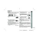
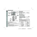
Remote control
!
Battery installation
Precautions for battery use:
"
Replace all old batteries with new ones at the same time.
"
Do not mix old and new batteries.
"
Remove the batteries if the unit is not to be used for long periods
of time. This will prevent potential damage due to battery leak-
age.
of time. This will prevent potential damage due to battery leak-
age.
Caution:
"
Do not use rechargeable batteries (nickel-cadmium battery, etc.).
"
Installing the batteries incorrectly may cause the unit to malfunc-
tion.
tion.
Notes concerning use:
"
Replace the batteries if the operating distance is reduced or if the
operation becomes erratic. Purchase 2 "AA" size batteries (UM/
SUM-3, R6, HP-7 or similar).
operation becomes erratic. Purchase 2 "AA" size batteries (UM/
SUM-3, R6, HP-7 or similar).
"
Periodically clean the transmitter on the remote control and the
sensor on the unit with a soft cloth.
sensor on the unit with a soft cloth.
"
Exposing the sensor on the unit to strong light may interfere with
operation. Change the lighting or the direction of the unit.
operation. Change the lighting or the direction of the unit.
"
Keep the remote control away from moisture, heat, shock, and
vibrations.
vibrations.
!
Test of the remote control
Check the remote control after checking all the connections (see
pages 7 - 9).
Point the remote control directly at the remote sensor on the unit.
pages 7 - 9).
Point the remote control directly at the remote sensor on the unit.
The remote control can be used within the range shown below:
Press the ON/STAND-BY button. Does the power turn on? Now,
you can enjoy music.
Press the ON/STAND-BY button. Does the power turn on? Now,
you can enjoy music.
1
Open the battery cover.
2
Insert the supplied batteries according to the direction indi-
cated in the battery compartment.
cated in the battery compartment.
When inserting or removing the batteries, push them towards the
battery terminals.
3
Close the battery cover.
0.2 m - 6 m
(8" - 20')
(8" - 20')
Remote sensor
Display

