Sharp CD-ES222E (serv.man2) Service Manual ▷ View online
– 3 –
CD-ES222H/ES222E
FOR A COMPLETE DESCRIPTION OF THE OPERATION OF THIS UNIT, PLEASE REFER
TO THE OPERATION MANUAL.
TO THE OPERATION MANUAL.
SPECIFICATIONS
Specifications for this model are subject to change without
prior notice.
prior notice.
Ge
■
■
■
■
■
■
neral
Amplifier
Power source
AC 230 V, 50 Hz
Power
consumption
consumption
Power on: 50 W
Power stand-by: 0.6 W (*)
Dimensions
Width: 270 mm (10-5/8")
Height: 305 mm (12")
Depth: 342 mm (13-1/2")
Height: 305 mm (12")
Depth: 342 mm (13-1/2")
Weight
5.9 kg (13.0 lbs.)
( * )This power consumption value is obtained when the demonstra-
tion mode is cancelled in the power stand-by mode. Refer to
page 8 to cancel the demonstration mode.
page 8 to cancel the demonstration mode.
Output power
PMPO: 120 W
MPO: 60 W (30 W + 30 W) (DIN 45 324)
RMS: 40 W (20 W + 20 W) (DIN 45 324)
RMS: 30 W (15 W + 15 W) (DIN 45 500)
Output terminals
Speakers: 8 ohms
Headphones: 16 - 50 ohms (recommended:
32 ohms)
32 ohms)
Input terminals
Video/Auxiliary (audio signal): 500 mV/47 k
ohms
ohms
CD player
Tuner
Cassette deck
Speaker
Type
3-disc multi-play compact disc player
Signal readout
Non-contact, 3-beam semiconductor laser
pickup
pickup
D/A converter
1-bit D/A converter
Frequency
response
response
20 - 20,000 Hz
Dynamic range
90 dB (1 kHz)
Frequency range
FM: 87.5 - 108 MHz
AM: 522 - 1,620 kHz
Frequency
response
response
125 - 8,000 Hz (normal tape)
Signal/noise ratio
50 dB (TAPE 1, playback)
50 dB (TAPE 2, recording/playback)
50 dB (TAPE 2, recording/playback)
Wow and flutter
0.5 % (DIN 45 511)
Type
2-way type speaker system
Tweeter
10 cm (4") woofer
Maximum input
power
power
40 W
Rated input power
20 W
Impedance
8 ohms
Dimensions
Width: 200 mm (7-7/8")
Height: 305 mm (12")
Depth: 175 mm (6-7/8")
Height: 305 mm (12")
Depth: 175 mm (6-7/8")
Weight
2.5 kg (5.5 lbs.)/each
Ge
■
■
■
neral
Amplifier
Power source
AC 230 - 240 V, 50 Hz
Power
consumption
consumption
50 W
Dimensions
Width: 270 mm (10-5/8")
Height: 305 mm (12")
Depth: 342 mm (13-1/2")
Height: 305 mm (12")
Depth: 342 mm (13-1/2")
Weight
5.8 kg (12.8 lbs.)
Output power
RMS: 40 W (20 W + 20 W) (10 % T.H.D.)
RMS: 30 W (15 W + 15 W) (0.9 % T.H.D.)
Output terminals
Speakers: 8 ohms
Headphones: 16 - 50 ohms (recommended:
32 ohms)
32 ohms)
Input terminals
Video/Auxiliary (audio signal): 500 mV/47 k
ohms
ohms
CD player
Tun
■
■
■
er
Cassette deck
Speaker
Type
3-disc multi-play compact disc player
Signal readout
Non-contact, 3-beam semiconductor laser
pickup
pickup
D/A converter
1-bit D/A converter
Frequency
response
response
20 - 20,000 Hz
Dynamic range
90 dB (1 kHz)
Frequency range
FM: 87.5 - 108 MHz
AM: 522 - 1,620 kHz
Frequency
response
response
125 - 8,000 Hz (normal tape)
Signal/noise ratio
50 dB (TAPE 1, playback)
50 dB (TAPE 2, recording/playback)
50 dB (TAPE 2, recording/playback)
Wow and flutter
0.3 % (WRMS)
Type
2-way type speaker system
Tweeter
10 cm (4") woofer
Maximum input
power
power
40 W
Rated input power
20 W
Impedance
8 ohms
Dimensions
Width: 200 mm (7-7/8")
Height: 305 mm (12")
Depth: 175 mm (6-7/8")
Height: 305 mm (12")
Depth: 175 mm (6-7/8")
Weight
2.5 kg (5.5 lbs.)/each
CD-ES222H
CD-ES222E
CD-ES222H/ES222E
– 4 –
NAMES OF PARTS
Fr
■
ont panel
1. Disc Tray
2. Timer Set Indicator
3. Memory/Set Button
4. On/Stand-by Button
5. Clock Button
6. Timer/Sleep Button
7. Tuning and Time Up Button
8. Tuning and Time Down Button
9. Headphone Socket
2. Timer Set Indicator
3. Memory/Set Button
4. On/Stand-by Button
5. Clock Button
6. Timer/Sleep Button
7. Tuning and Time Up Button
8. Tuning and Time Down Button
9. Headphone Socket
10. Tape 2 Record Pause Button
11. Tape 1 Cassette Compartment
12. Equaliser Mode Select Button
13. Extra Bass/Demo Mode Button
14. Volume Up and Down Buttons
15. Disc Tray Open/Close Button
16. Disc Skip Button
17. Tape 2 Cassette Compartment
18. CD Button
19. Tape (1 2) Button
20. CD or Tape Stop Button
21. CD Track Down or Fast Reverse, Tape 2 Rewind,
Tuner Preset Down Button
22. Tuner (Band) Button
23. Video/Auxiliary Button
24. CD Play or Repeat, Tape Play Button
25. CD Track Up or Fast Forward, Tape 2 Fast Forward,
23. Video/Auxiliary Button
24. CD Play or Repeat, Tape Play Button
25. CD Track Up or Fast Forward, Tape 2 Fast Forward,
Tuner Preset Up Button
3
4
5
4
5
2
1
6
11
7
8
9
8
9
10
12
16
14
15
17
13
22
23
23
24
25
25
18
19
19
20
21
21
Dis
■
■
■
play
1. Disc Number Indicators
2. CD Play Indicator
3. Tape Play Indicator
4. FM Stereo Mode Indicator
5. FM Stereo Receiving Indicator
6. Memory Indicator
7. Extra Bass Indicator
8. Timer Recording Indicator
9. Timer Play Indicator
2. CD Play Indicator
3. Tape Play Indicator
4. FM Stereo Mode Indicator
5. FM Stereo Receiving Indicator
6. Memory Indicator
7. Extra Bass Indicator
8. Timer Recording Indicator
9. Timer Play Indicator
10. CD Pause Indicator
11. CD Repeat Play Indicator
12. Tape 2 Record Indicator
13. Sleep Indicator
11. CD Repeat Play Indicator
12. Tape 2 Record Indicator
13. Sleep Indicator
Rear panel
1. Video/Auxiliary (Audio Signal) Input Sockets
2. AC Power Input Socket
3. FM/AM Loop Aerial Socket
4. Speaker Terminals
2. AC Power Input Socket
3. FM/AM Loop Aerial Socket
4. Speaker Terminals
Speaker system
1. Tweeter
2. Bass Reflex Ducts
3. Woofer
4. Speaker Wire
2. Bass Reflex Ducts
3. Woofer
4. Speaker Wire
1
3
4
2
2
1
3
4 5 6 7
8
9
13
12
10 11
4
2
2
3
1
– 5 –
CD-ES222H/ES222E
Remote c
■
ontrol
1. Remote Control Transmitter
2. On/Stand-by Button
3. CD Button
4. Tape (1 2) Button
5. Memory Button
6. Programme Clear Button
7. Tuning and Time Down Button
8. CD Track Down or Fast Reverse, Tape 2 Rewind,
2. On/Stand-by Button
3. CD Button
4. Tape (1 2) Button
5. Memory Button
6. Programme Clear Button
7. Tuning and Time Down Button
8. CD Track Down or Fast Reverse, Tape 2 Rewind,
Tuner Preset Down Button
9. CD or Tape Stop Button
10. Equaliser Mode Select Button
11. Disc Number Select Buttons
12. Tuner (Band) Button
13. Video/Auxiliary Button
14. CD Random Button
15. CD Track Up or Fast Forward, Tape 2 Fast Forward,
11. Disc Number Select Buttons
12. Tuner (Band) Button
13. Video/Auxiliary Button
14. CD Random Button
15. CD Track Up or Fast Forward, Tape 2 Fast Forward,
Tuner Preset Up Button
16. Tuning and Time Up Button
17. CD Play or Repeat, Tape Play Button
18. Tape 2 Record Pause Button
19. CD Pause Button
20. Extra Bass Button
21. Volume Up and Down Buttons
17. CD Play or Repeat, Tape Play Button
18. Tape 2 Record Pause Button
19. CD Pause Button
20. Extra Bass Button
21. Volume Up and Down Buttons
1
2
3
4
5
6
7
7
8
9
9
10
14
12
13
11
17
18
21
20
19
15
16
16
CD-ES222H/ES222E
– 6 –
DISASSEMBLY
Caution on Disassembly
Follow the below-mentioned notes when disassembling
the unit and reassembling it, to keep it safe and ensure
excellent performance:
1. Take cassette tape and compact disc out of the unit.
2. Be sure to remove the power supply plug from the wall
Follow the below-mentioned notes when disassembling
the unit and reassembling it, to keep it safe and ensure
excellent performance:
1. Take cassette tape and compact disc out of the unit.
2. Be sure to remove the power supply plug from the wall
outlet before starting to disassemble the unit.
3. Take off nylon bands or wire holders where they need to
be removed when disassembling the unit. After servicing
the unit, be sure to rearrange the leads where they were
before disassembling.
the unit, be sure to rearrange the leads where they were
before disassembling.
4. Take sufficient care on static electricity of integrated
circuits and other circuits when servicing.
Figure 6-2
Figure 6-1
Figure 6-3
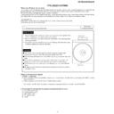
Note 1: How to open the changer manually. (Fig. 6-3)
1. In this state, turn fully the loading Gear in the arrow direction
1. In this state, turn fully the loading Gear in the arrow direction
through the hold on the loading tray bottom.
2. After that,push forward the loading tray.
Side Panel
(Right)
(Right)
Side Panel
(Left)
(Left)
Top Cabinet
Front
Panel
Panel
(A1)x2
ø3x16mm
ø3x16mm
(A1)x2
ø3x16mm
ø3x16mm
(B1)x2
ø3x8mm
ø3x8mm
(B1)x2
ø3x8mm
ø3x8mm
(B1)x4
ø3x10mm
ø3x10mm
(A1)x1
ø3x8mm
ø3x8mm
Rear Panel
1
1
2
2
(D1)x7
ø3x8mm
ø3x8mm
(D1)x2
ø3x10mm
ø3x10mm
(E1)x2
ø3x6mm
ø3x6mm
CD Player Unit
CD Tray Cover
(E1)x1
ø3x10mm
ø3x10mm
(C2)x1
(C3)x1
CD Servo
PWB
PWB
(C1)x1
Pull
(C2)x1
Pull
Main
PWB
PWB
Rear
Panel
Panel
CD Player Unit
(Bottom View)
Loading Gear
Front Side
or
Note 2:
1. After removing the connector for the optical pickup from the
1. After removing the connector for the optical pickup from the
connector, wrap the conductive aluminium foil around the front end
of the connector so as to protect the optical pickup from electro-
static damage.
of the connector so as to protect the optical pickup from electro-
static damage.
1
Top Cabinet
1. Screw ...................... (A1) x5
6-1
2
Side Panel
1. Screw ...................... (B1) x8
6-1
(Left/Right)
3
CD Player Unit
1. Turn on the power supply, ..
6-2
open the disc tray, take out
the CD tray cover, and close.
the CD tray cover, and close.
.................................. (Note 1)
2. CD Tray Cover ........ (C1) x1
3. Hook ........................ (C2) x2
4. Socket ..................... (C3) x1
5. Socket ..................... (C4) x2
3. Hook ........................ (C2) x2
4. Socket ..................... (C3) x1
5. Socket ..................... (C4) x2
7-1
4
Rear Panel
1. Screw ...................... (D1) x9
6-2
5
Main PWB
1. Screw ...................... (E1) x3
6-2
2. Socket ..................... (E2) x8
7-1
3. Socket ..................... (E3) x2
7-2
6
Front Panel
1. Screw ....................... (F1) x3
7-1
2. Hook ......................... (F2) x2
3. Socket ...................... (F3) x1
3. Socket ...................... (F3) x1
7
Display PWB
1. Screw .................... (G1) x13
7-2
8
Tape Mechanism 1. Open the cassette holder.
7-2
2. Screw...................... (H1) x8
9
Headphones PWB 1. Screw ....................... (J1) x1
7-2
10
CD Servo PWB
1. Screw ...................... (K1) x4
7-3
(Note 2)
2. Socket ..................... (K2) x3
3. Flat Cable ............... (K3) x1
4. Solder ...................... (K4) x2
3. Flat Cable ............... (K3) x1
4. Solder ...................... (K4) x2
11
Turntable
1. Screw ....................... (L1) x1
7-4
2. Spacer ...................... (L2) x1
12
Loading Tray
1. Push forward the loading tray.
7-4
2. Inserting the flat head into the
hole, push in the direction indi-
cated by the arrow. ... (M1) x2
cated by the arrow. ... (M1) x2
13
CD Mechanism
1. Hook ........................ (N1) x2
7-5
Block
STEP
REMOVAL
PROCEDURE
FIGURE

